Brother International DCP-1400 Service Manual - Page 121
Maintenance, Functions
 |
View all Brother International DCP-1400 manuals
Add to My Manuals
Save this manual to your list of manuals |
Page 121 highlights
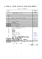
2. LIST OF MAINTENANCE-MODE FUNCTIONS Function Code 01 02 03 04 05 06 07 08 09 10 11 12 13 14 15 16 32 55 74 79 82 87 91 99 Maintenance-mode Functions Function EEPROM Parameter Initialization Reference Subsection (Page) 3.1 (V-5) Printout of Scanning Compensation Data ADF* Performance Test Test Pattern 1 Firmware Switch Setting Printout of Firmware Switch Data Operational Check of LCD Operational Check of Control Panel PCB (Check of Keys and Buttons) 3.2 (V-6) 3.3 (V-8) 3.4 (V-9) 3.5 (V-10) 3.5 (V-12) 3.6 (V-13) 3.7 (V-13) Sensor Operational Check CCD Scanner Area Setting EEPROM Customizing Erasure of Received FAX Messages Temporarily Stored in the Flash Memory (Not applicable to the American version) Machine Error Code Indication Output of Transmission Log to the Telephone Line (Not applicable to machines w/o fax) EEPROM Parameter Initialization (except the telephone number storage area) Exit from the Maintenance Mode 3.8 (V-15) 3.9 (V-16) 3.10 (V-16) 3.11 (V-17) 3.12 (V-17) 3.13 (V-18) 3.1 (V-5) ---- (V-1) * ADF: Automatic document feeder V - 2
-
 1
1 -
2
-
3
-
4
-
5
-
6
-
7
-
8
-
9
-
10
-
11
-
12
-
13
-
14
-
15
-
16
-
17
-
18
-
19
-
20
-
21
-
22
-
23
-
24
-
25
-
26
-
27
-
28
-
29
-
30
-
31
-
32
-
33
-
34
-
35
-
36
-
37
-
38
-
39
-
40
-
41
-
42
-
43
-
44
-
45
-
46
-
47
-
48
-
49
-
50
-
51
-
52
-
53
-
54
-
55
-
56
-
57
-
58
-
59
-
60
-
61
-
62
-
63
-
64
-
65
-
66
-
67
-
68
-
69
-
70
-
71
-
72
-
73
-
74
-
75
-
76
-
77
-
78
-
79
-
80
-
81
-
82
-
83
-
84
-
85
-
86
-
87
-
88
-
89
-
90
-
91
-
92
-
93
-
94
-
95
-
96
-
97
-
98
-
99
-
100
-
101
-
102
-
103
-
104
-
105
-
106
-
107
-
108
-
109
-
110
-
111
-
112
-
113
-
114
-
115
-
 116
116 -
 117
117 -
 118
118 -
 119
119 -
 120
120 -
 121
121 -
 122
122 -
 123
123 -
 124
124 -
 125
125 -
 126
126 -
127
-
128
-
129
-
130
-
131
-
132
-
133
-
134
-
135
-
136
-
137
-
138
-
139
-
140
-
141
-
142
-
143
-
144
-
145
-
146
-
147
-
148
-
149
-
150
-
151
-
152
-
153
-
154
-
155
-
156
-
157
-
158
-
159
-
160
-
161
-
162
-
163
-
164
-
165
-
166
-
167
-
168
-
169
-
170
-
171
-
172
-
173
-
174
-
175
-
176
-
177
-
178
-
179
-
180
-
181
-
182
-
183
-
184
-
185
-
186
-
187
-
188
-
189
-
190
-
191
-
192
-
193
-
194
-
195
-
196
-
197
-
198
-
199
-
200
-
201
-
202
-
203
-
204
-
205
-
206
-
207
-
208
-
209
-
210
-
211
-
212
-
213
-
214
-
215
-
216
-
217
-
218
-
219
-
220
-
221
-
222
-
223
-
224
-
225
-
226
-
227
-
228
-
229
 |
 |
