Brother International DCP-1400 Service Manual - Page 43
Disassembly/reassembly, Lubrication, Contents
 |
View all Brother International DCP-1400 manuals
Add to My Manuals
Save this manual to your list of manuals |
Page 43 highlights
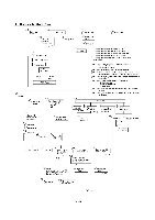
CHAPTER IV. DISASSEMBLY/REASSEMBLY AND LUBRICATION CONTENTS 1. DISASSEMBLY/REASSEMBLY ■ Safety Precautions ■ Preparation ■ How to Access the Object Component ■ Disassembly Order Flow 1.1 Lower Rear Cover 1.2 Access Plates R and F 1.3 Paper Cassette 1.4 Document Tray ASSY 1.5 Upper Rear Cover 1.6 ADF Unit [ Disassembling the ADF Unit ] 1.7 Scanner Unit and Control Panel ASSY [ Disassembling the Scanner Unit ] [ Disassembling the Control Panel ASSY ] 1.8 Relay PCB 1.9 Speaker 1.10 Scanner Mount 1.11 Paper Sub Tray and Tray Holder 1.12 VC Cover, VC Bracket, and VC Connector PCB (for models supporting video capture) 1.13 Front Cover Front Sub Cover (for models not supporting video capture) 1.14 Outer Chute and Paper Pinch Rollers 1.15 Main Cover 1.16 Switch Cover (for models not equipped with a power switch) 1.17 Laser Unit 1.18 Heat-fixing Unit and FU Lamp 1.19 Fan 1.20 Drive Gear ASSY and Main Motor ASSY 1.21 NCU Shield and NCU PCB* 1.22 Bottom Plate, Main PCB, and Bottom Insulation Film 1.23 Low-voltage Power Supply PCB and Power Inlet IV-1 IV-1 IV-2 IV-2 IV-3 IV-4 IV-4 IV-5 IV-6 IV-8 IV-9 IV-11 IV-16 IV-19 IV-24 IV-25 IV-26 IV-27 IV-30 IV-31 IV-32 IV-33 IV-34 IV-35 IV-36 IV-37 IV-51 IV-53 IV-55 IV-57 IV-61 i
-
 1
1 -
2
-
3
-
4
-
5
-
6
-
7
-
8
-
9
-
10
-
11
-
12
-
13
-
14
-
15
-
16
-
17
-
18
-
19
-
20
-
21
-
22
-
23
-
24
-
25
-
26
-
27
-
28
-
29
-
30
-
31
-
32
-
33
-
34
-
35
-
36
-
37
-
 38
38 -
 39
39 -
 40
40 -
 41
41 -
 42
42 -
 43
43 -
 44
44 -
 45
45 -
 46
46 -
 47
47 -
 48
48 -
49
-
50
-
51
-
52
-
53
-
54
-
55
-
56
-
57
-
58
-
59
-
60
-
61
-
62
-
63
-
64
-
65
-
66
-
67
-
68
-
69
-
70
-
71
-
72
-
73
-
74
-
75
-
76
-
77
-
78
-
79
-
80
-
81
-
82
-
83
-
84
-
85
-
86
-
87
-
88
-
89
-
90
-
91
-
92
-
93
-
94
-
95
-
96
-
97
-
98
-
99
-
100
-
101
-
102
-
103
-
104
-
105
-
106
-
107
-
108
-
109
-
110
-
111
-
112
-
113
-
114
-
115
-
116
-
117
-
118
-
119
-
120
-
121
-
122
-
123
-
124
-
125
-
126
-
127
-
128
-
129
-
130
-
131
-
132
-
133
-
134
-
135
-
136
-
137
-
138
-
139
-
140
-
141
-
142
-
143
-
144
-
145
-
146
-
147
-
148
-
149
-
150
-
151
-
152
-
153
-
154
-
155
-
156
-
157
-
158
-
159
-
160
-
161
-
162
-
163
-
164
-
165
-
166
-
167
-
168
-
169
-
170
-
171
-
172
-
173
-
174
-
175
-
176
-
177
-
178
-
179
-
180
-
181
-
182
-
183
-
184
-
185
-
186
-
187
-
188
-
189
-
190
-
191
-
192
-
193
-
194
-
195
-
196
-
197
-
198
-
199
-
200
-
201
-
202
-
203
-
204
-
205
-
206
-
207
-
208
-
209
-
210
-
211
-
212
-
213
-
214
-
215
-
216
-
217
-
218
-
219
-
220
-
221
-
222
-
223
-
224
-
225
-
226
-
227
-
228
-
229
 |
 |
