Brother International DCP-1400 Service Manual - Page 111
screwdriver
 |
View all Brother International DCP-1400 manuals
Add to My Manuals
Save this manual to your list of manuals |
Page 111 highlights
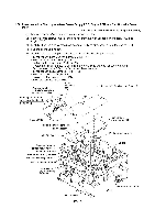
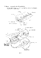
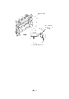
1.27 Paper Feed Roller ASSY (1) Unhook the latch (arrow 0) provided on the underside of the plastic frame by using a small flat screwdriver and pull out the gear 21 (arrow O). (2) Place the main chassis rightside up. (3) At the right end of the paper feed roller shaft, pull up the pawl of the bushing (arrow 0) with the tip of a flat screwdriver and move the paper feed roller ASSY to the left (arrow O). Then take out the bushing and paper feed roller ASSY. (4) Remove the joint (arrow e). Fitting the D-shaped ends with each other Joint D-shaped end of the paper feed roller ASSY D-shaped end of gear 21 Main chassis placed rightside up Gear 21 ii Joint Pawled bushing Paper feed roller ASSY (Front) Cassette sensor actuator Latch Engine PCB ■ Reassembling Notes • When setting the gear 21 back into place, insert it and turn it so that its D-shaped end becomes fitted with the D-shaped end of the paper feed roller ASSY. IV - 67
-
 1
1 -
2
-
3
-
4
-
5
-
6
-
7
-
8
-
9
-
10
-
11
-
12
-
13
-
14
-
15
-
16
-
17
-
18
-
19
-
20
-
21
-
22
-
23
-
24
-
25
-
26
-
27
-
28
-
29
-
30
-
31
-
32
-
33
-
34
-
35
-
36
-
37
-
38
-
39
-
40
-
41
-
42
-
43
-
44
-
45
-
46
-
47
-
48
-
49
-
50
-
51
-
52
-
53
-
54
-
55
-
56
-
57
-
58
-
59
-
60
-
61
-
62
-
63
-
64
-
65
-
66
-
67
-
68
-
69
-
70
-
71
-
72
-
73
-
74
-
75
-
76
-
77
-
78
-
79
-
80
-
81
-
82
-
83
-
84
-
85
-
86
-
87
-
88
-
89
-
90
-
91
-
92
-
93
-
94
-
95
-
96
-
97
-
98
-
99
-
100
-
101
-
102
-
103
-
104
-
105
-
 106
106 -
 107
107 -
 108
108 -
 109
109 -
 110
110 -
 111
111 -
 112
112 -
 113
113 -
 114
114 -
 115
115 -
 116
116 -
117
-
118
-
119
-
120
-
121
-
122
-
123
-
124
-
125
-
126
-
127
-
128
-
129
-
130
-
131
-
132
-
133
-
134
-
135
-
136
-
137
-
138
-
139
-
140
-
141
-
142
-
143
-
144
-
145
-
146
-
147
-
148
-
149
-
150
-
151
-
152
-
153
-
154
-
155
-
156
-
157
-
158
-
159
-
160
-
161
-
162
-
163
-
164
-
165
-
166
-
167
-
168
-
169
-
170
-
171
-
172
-
173
-
174
-
175
-
176
-
177
-
178
-
179
-
180
-
181
-
182
-
183
-
184
-
185
-
186
-
187
-
188
-
189
-
190
-
191
-
192
-
193
-
194
-
195
-
196
-
197
-
198
-
199
-
200
-
201
-
202
-
203
-
204
-
205
-
206
-
207
-
208
-
209
-
210
-
211
-
212
-
213
-
214
-
215
-
216
-
217
-
218
-
219
-
220
-
221
-
222
-
223
-
224
-
225
-
226
-
227
-
228
-
229
 |
 |
