Brother International DCP-1400 Service Manual - Page 52
Brother International DCP-1400 Manual
 |
View all Brother International DCP-1400 manuals
Add to My Manuals
Save this manual to your list of manuals |
Page 52 highlights
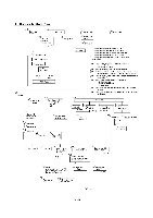
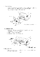
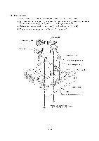
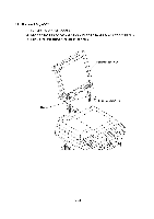
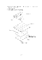
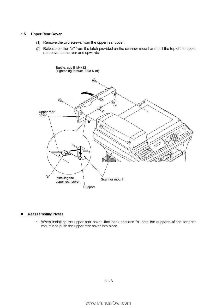
1.5 Upper Rear Cover (1) Remove the two screws from the upper rear cover. (2) Release section "a" from the latch provided on the scanner mount and pull the top of the upper rear cover to the rear and upwards. Taptite, cup B M4x12 (Tightening torque: 0.98 NI•m) Upper rear cover ilorimmw O 0O0000 O 00 0 O C0) 00 00000000",--- 0 0 0 o ' oS) -) 0 Installing the upper rear cover Support Scanner mount • Reassembling Notes • When installing the upper rear cover, first hook sections "b" onto the supports of the scanner mount and push the upper rear cover into place. IV - 8
-
 1
1 -
2
-
3
-
4
-
5
-
6
-
7
-
8
-
9
-
10
-
11
-
12
-
13
-
14
-
15
-
16
-
17
-
18
-
19
-
20
-
21
-
22
-
23
-
24
-
25
-
26
-
27
-
28
-
29
-
30
-
31
-
32
-
33
-
34
-
35
-
36
-
37
-
38
-
39
-
40
-
41
-
42
-
43
-
44
-
45
-
46
-
 47
47 -
 48
48 -
 49
49 -
 50
50 -
 51
51 -
 52
52 -
 53
53 -
 54
54 -
 55
55 -
 56
56 -
 57
57 -
58
-
59
-
60
-
61
-
62
-
63
-
64
-
65
-
66
-
67
-
68
-
69
-
70
-
71
-
72
-
73
-
74
-
75
-
76
-
77
-
78
-
79
-
80
-
81
-
82
-
83
-
84
-
85
-
86
-
87
-
88
-
89
-
90
-
91
-
92
-
93
-
94
-
95
-
96
-
97
-
98
-
99
-
100
-
101
-
102
-
103
-
104
-
105
-
106
-
107
-
108
-
109
-
110
-
111
-
112
-
113
-
114
-
115
-
116
-
117
-
118
-
119
-
120
-
121
-
122
-
123
-
124
-
125
-
126
-
127
-
128
-
129
-
130
-
131
-
132
-
133
-
134
-
135
-
136
-
137
-
138
-
139
-
140
-
141
-
142
-
143
-
144
-
145
-
146
-
147
-
148
-
149
-
150
-
151
-
152
-
153
-
154
-
155
-
156
-
157
-
158
-
159
-
160
-
161
-
162
-
163
-
164
-
165
-
166
-
167
-
168
-
169
-
170
-
171
-
172
-
173
-
174
-
175
-
176
-
177
-
178
-
179
-
180
-
181
-
182
-
183
-
184
-
185
-
186
-
187
-
188
-
189
-
190
-
191
-
192
-
193
-
194
-
195
-
196
-
197
-
198
-
199
-
200
-
201
-
202
-
203
-
204
-
205
-
206
-
207
-
208
-
209
-
210
-
211
-
212
-
213
-
214
-
215
-
216
-
217
-
218
-
219
-
220
-
221
-
222
-
223
-
224
-
225
-
226
-
227
-
228
-
229
 |
 |
1.5
Upper
Rear
Cover
(1)
Remove
the
two
screws
from
the
upper
rear
cover.
(2)
Release
section
"a"
from
the
latch
provided
on
the
scanner
mount
and
pull
the
top
of
the
upper
rear
cover
to
the
rear
and
upwards.
Taptite,
cup
B
M4x12
(Tightening
torque:
0.98
NI•m)
ilorimmw
Upper
rear
cover
Installing
the
upper
rear
cover
Support
•
Reassembling
Notes
O
Scanner
mount
0
00
O00
O
0
0 0
O
C)
0
o
'
o
S)
000
0
00
0,-
-
)
00
00"--
0
0
0
•
When
installing
the
upper
rear
cover,
first
hook
sections
"b"
onto
the
supports
of
the
scanner
mount
and
push the
upper
rear
cover
into
place.
IV
-
8