Brother International DCP-1400 Service Manual - Page 99
Provided, models, supporting, facsimile, function., harness, provided, video, capture, Tightening,
 |
View all Brother International DCP-1400 manuals
Add to My Manuals
Save this manual to your list of manuals |
Page 99 highlights
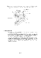
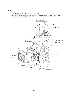
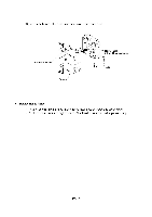
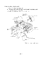
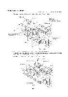
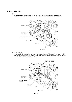
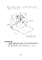
1.21 NCU Shield and NCU PCB* (*Provided on models supporting facsimile function.) (1) Remove three screws from the NCU shield, then take off the NCU shield. NCU shield 'Y % 9 99 9 9 9 9 9% VC harness (provided on models supporting video capture) CIS harness Taptite, cup S M3x6 (Tightening torque: 0.5 N•rn) (Rear) 99 9% 9 9 9 Main-relay (motors) 0 harness Main chassis USA version: Disconnect the main-NCU harness from the main PCB. European version: Disconnect the main-NCU harness and main-NCU harness 2 from the main PCB. See the illustration given on the next page. Remove the screw from the NCU PCB and take out the PCB. Taptite, cup S M3x6 Main-NCU harness ? NCU PCB* Main PCB 9 •sv- 79 % 9 99 0 Main chassis (Rear) IV - 55
-
 1
1 -
2
-
3
-
4
-
5
-
6
-
7
-
8
-
9
-
10
-
11
-
12
-
13
-
14
-
15
-
16
-
17
-
18
-
19
-
20
-
21
-
22
-
23
-
24
-
25
-
26
-
27
-
28
-
29
-
30
-
31
-
32
-
33
-
34
-
35
-
36
-
37
-
38
-
39
-
40
-
41
-
42
-
43
-
44
-
45
-
46
-
47
-
48
-
49
-
50
-
51
-
52
-
53
-
54
-
55
-
56
-
57
-
58
-
59
-
60
-
61
-
62
-
63
-
64
-
65
-
66
-
67
-
68
-
69
-
70
-
71
-
72
-
73
-
74
-
75
-
76
-
77
-
78
-
79
-
80
-
81
-
82
-
83
-
84
-
85
-
86
-
87
-
88
-
89
-
90
-
91
-
92
-
93
-
 94
94 -
 95
95 -
 96
96 -
 97
97 -
 98
98 -
 99
99 -
 100
100 -
 101
101 -
 102
102 -
 103
103 -
 104
104 -
105
-
106
-
107
-
108
-
109
-
110
-
111
-
112
-
113
-
114
-
115
-
116
-
117
-
118
-
119
-
120
-
121
-
122
-
123
-
124
-
125
-
126
-
127
-
128
-
129
-
130
-
131
-
132
-
133
-
134
-
135
-
136
-
137
-
138
-
139
-
140
-
141
-
142
-
143
-
144
-
145
-
146
-
147
-
148
-
149
-
150
-
151
-
152
-
153
-
154
-
155
-
156
-
157
-
158
-
159
-
160
-
161
-
162
-
163
-
164
-
165
-
166
-
167
-
168
-
169
-
170
-
171
-
172
-
173
-
174
-
175
-
176
-
177
-
178
-
179
-
180
-
181
-
182
-
183
-
184
-
185
-
186
-
187
-
188
-
189
-
190
-
191
-
192
-
193
-
194
-
195
-
196
-
197
-
198
-
199
-
200
-
201
-
202
-
203
-
204
-
205
-
206
-
207
-
208
-
209
-
210
-
211
-
212
-
213
-
214
-
215
-
216
-
217
-
218
-
219
-
220
-
221
-
222
-
223
-
224
-
225
-
226
-
227
-
228
-
229
 |
 |

1.21
NCU
Shield
and
NCU
PCB*
(*Provided
on
models
supporting
facsimile
function.)
(1)
Remove
three
screws
from
the
NCU
shield,
then
take
off
the
NCU
shield.
NCU
shield
VC
harness
(provided
on
models
supporting
video
capture)
CIS
harness
'Y
%
9
99
9
9
9
9
9
%
Taptite,
cup
S
M3x6
(Tightening
torque:
0.5
N•rn)
9
9
9
%
9
9
9
(Rear)
0
Main
chassis
Main
-relay
(motors)
harness
USA
version:
Disconnect
the
main-NCU
harness
from
the
main
PCB.
European
version:
Disconnect
the
main-NCU
harness
and
main-NCU
harness
2
from
the
main
PCB.
See
the
illustration
given
on
the
next
page.
Remove
the
screw
from
the
NCU
PCB
and
take
out
the
PCB.
Taptite,
cup
S
M3x6
Main-NCU
harness
?
NCU
PCB*
Main
PCB
9
•
7
sv-
9
9
9
%
9
Main
chassis
(Rear)
IV
-
55
0