Brother International DCP-1400 Service Manual - Page 49
bosses
 |
View all Brother International DCP-1400 manuals
Add to My Manuals
Save this manual to your list of manuals |
Page 49 highlights
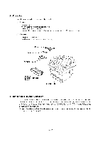
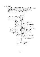
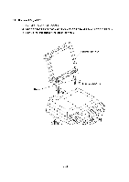
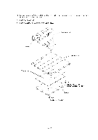
1.3 Paper Cassette (1) Pull the pressure plate release lever to the front to release the pressure plate. (2) Fully slide the side guide (R or L) inwards (in the direction of arrow 0) and remove the screw. Then release the latches (arrow 0) and pull up the side guide (arrow 0). (3) Release the pressure plate from the bosses (arrow ®) and remove it (arrow 0). (4) Fully slide the paper rear guide to the front and lift it up (arrow 6). Paper rear guide Side guide L o Side guide R k(1 1 Separation pad Separation pad support Separation pad spring I Boss Pressure plate Paper cassette Hook Pressure plate release lever Screw, pan cup B M2.6x5 (Tightening torque: 0.3±0.1 KI•rn) IV - 5
-
 1
1 -
2
-
3
-
4
-
5
-
6
-
7
-
8
-
9
-
10
-
11
-
12
-
13
-
14
-
15
-
16
-
17
-
18
-
19
-
20
-
21
-
22
-
23
-
24
-
25
-
26
-
27
-
28
-
29
-
30
-
31
-
32
-
33
-
34
-
35
-
36
-
37
-
38
-
39
-
40
-
41
-
42
-
43
-
 44
44 -
 45
45 -
 46
46 -
 47
47 -
 48
48 -
 49
49 -
 50
50 -
 51
51 -
 52
52 -
 53
53 -
 54
54 -
55
-
56
-
57
-
58
-
59
-
60
-
61
-
62
-
63
-
64
-
65
-
66
-
67
-
68
-
69
-
70
-
71
-
72
-
73
-
74
-
75
-
76
-
77
-
78
-
79
-
80
-
81
-
82
-
83
-
84
-
85
-
86
-
87
-
88
-
89
-
90
-
91
-
92
-
93
-
94
-
95
-
96
-
97
-
98
-
99
-
100
-
101
-
102
-
103
-
104
-
105
-
106
-
107
-
108
-
109
-
110
-
111
-
112
-
113
-
114
-
115
-
116
-
117
-
118
-
119
-
120
-
121
-
122
-
123
-
124
-
125
-
126
-
127
-
128
-
129
-
130
-
131
-
132
-
133
-
134
-
135
-
136
-
137
-
138
-
139
-
140
-
141
-
142
-
143
-
144
-
145
-
146
-
147
-
148
-
149
-
150
-
151
-
152
-
153
-
154
-
155
-
156
-
157
-
158
-
159
-
160
-
161
-
162
-
163
-
164
-
165
-
166
-
167
-
168
-
169
-
170
-
171
-
172
-
173
-
174
-
175
-
176
-
177
-
178
-
179
-
180
-
181
-
182
-
183
-
184
-
185
-
186
-
187
-
188
-
189
-
190
-
191
-
192
-
193
-
194
-
195
-
196
-
197
-
198
-
199
-
200
-
201
-
202
-
203
-
204
-
205
-
206
-
207
-
208
-
209
-
210
-
211
-
212
-
213
-
214
-
215
-
216
-
217
-
218
-
219
-
220
-
221
-
222
-
223
-
224
-
225
-
226
-
227
-
228
-
229
 |
 |

1.3
Paper
Cassette
(1)
Pull
the
pressure
plate
release
lever
to
the
front
to
release
the
pressure
plate.
(2)
Fully
slide
the
side
guide
(R
or
L)
inwards
(in
the
direction
of
arrow
0)
and
remove
the
screw.
Then
release
the
latches
(arrow
0)
and
pull
up
the
side
guide
(arrow
0).
(3)
Release
the
pressure
plate
from
the
bosses
(arrow
®)
and
remove
it
(arrow
0).
(4)
Fully
slide
the
paper
rear
guide
to
the
front
and
lift
it
up
(arrow
6).
Paper
rear
guide
Side
guide
L
o
Side
guide
R
k(1
1
I
Separation pad
Separation pad
support
Separation
pad
spring
Boss
Hook
Pressure
plate
Paper
cassette
Pressure
plate
release
lever
Screw,
pan
cup
B
M2.6x5
(Tightening
torque:
0.3±0.1
KI•rn)
IV
-
5