Brother International DCP-1400 Service Manual - Page 97
Drive, Motor, Remove, screws, drive, ASSY., towards, while, taking, develop, joint, spring,
 |
View all Brother International DCP-1400 manuals
Add to My Manuals
Save this manual to your list of manuals |
Page 97 highlights
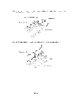
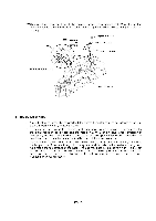
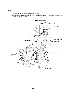
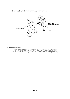
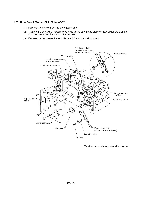
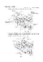
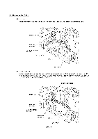
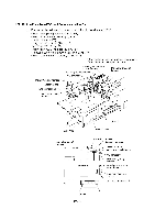
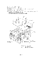
1.20 Drive Gear ASSY and Main Motor ASSY (1) Remove five screws from the drive gear ASSY. (2) Tilt the drive gear ASSY towards you while taking care not to drop the develop joint and spring, and then disconnect the main motor harness. (3) Remove the front cover link and idle gear 56 from the main chassis. Front cover link (Also acts as cover sensor actuator) VC harness* In-casing temperature sensor harness Main motor harness 00 (IA Main chassis Taptite, cup S M3x6 O cn / '0"\), Drive gear ASSY Idle gear 56 Polygon motor harness Laser flat cable Front cover link (Cover sensor actuator) Develop joint Spring *Provided on models supporting video capture IV - 53
-
 1
1 -
2
-
3
-
4
-
5
-
6
-
7
-
8
-
9
-
10
-
11
-
12
-
13
-
14
-
15
-
16
-
17
-
18
-
19
-
20
-
21
-
22
-
23
-
24
-
25
-
26
-
27
-
28
-
29
-
30
-
31
-
32
-
33
-
34
-
35
-
36
-
37
-
38
-
39
-
40
-
41
-
42
-
43
-
44
-
45
-
46
-
47
-
48
-
49
-
50
-
51
-
52
-
53
-
54
-
55
-
56
-
57
-
58
-
59
-
60
-
61
-
62
-
63
-
64
-
65
-
66
-
67
-
68
-
69
-
70
-
71
-
72
-
73
-
74
-
75
-
76
-
77
-
78
-
79
-
80
-
81
-
82
-
83
-
84
-
85
-
86
-
87
-
88
-
89
-
90
-
91
-
 92
92 -
 93
93 -
 94
94 -
 95
95 -
 96
96 -
 97
97 -
 98
98 -
 99
99 -
 100
100 -
 101
101 -
 102
102 -
103
-
104
-
105
-
106
-
107
-
108
-
109
-
110
-
111
-
112
-
113
-
114
-
115
-
116
-
117
-
118
-
119
-
120
-
121
-
122
-
123
-
124
-
125
-
126
-
127
-
128
-
129
-
130
-
131
-
132
-
133
-
134
-
135
-
136
-
137
-
138
-
139
-
140
-
141
-
142
-
143
-
144
-
145
-
146
-
147
-
148
-
149
-
150
-
151
-
152
-
153
-
154
-
155
-
156
-
157
-
158
-
159
-
160
-
161
-
162
-
163
-
164
-
165
-
166
-
167
-
168
-
169
-
170
-
171
-
172
-
173
-
174
-
175
-
176
-
177
-
178
-
179
-
180
-
181
-
182
-
183
-
184
-
185
-
186
-
187
-
188
-
189
-
190
-
191
-
192
-
193
-
194
-
195
-
196
-
197
-
198
-
199
-
200
-
201
-
202
-
203
-
204
-
205
-
206
-
207
-
208
-
209
-
210
-
211
-
212
-
213
-
214
-
215
-
216
-
217
-
218
-
219
-
220
-
221
-
222
-
223
-
224
-
225
-
226
-
227
-
228
-
229
 |
 |

1.20
Drive
Gear
ASSY
and
Main
Motor
ASSY
(1)
Remove
five
screws
from
the
drive
gear
ASSY.
(2)
Tilt
the
drive
gear
ASSY
towards
you
while
taking
care
not
to
drop
the
develop
joint
and
spring,
and
then
disconnect
the
main
motor
harness.
(3)
Remove
the
front
cover
link
and
idle
gear
56
from
the
main
chassis.
Taptite,
cup
S
M3x6
VC
harness*
In
-casing
temperature
sensor
harness
Main
motor
harness
00
O
cn
/
'0"\),
Drive
gear
ASSY
Idle
gear
56
IV
-
53
Front
cover
link
(Also
acts
as
cover
sensor
actuator)
(IA
Spring
Main
chassis
Polygon
motor
harness
Laser
flat
cable
Front
cover
link
(Cover
sensor
actuator)
Develop
joint
*Provided
on
models
supporting
video
capture