Brother International DCP-1400 Service Manual - Page 82
fixing, Heater, thermistor, harness, heater, Short, Latch, Engine, Front, Stepped, screw, Taptite
 |
View all Brother International DCP-1400 manuals
Add to My Manuals
Save this manual to your list of manuals |
Page 82 highlights
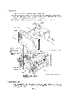
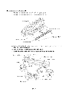
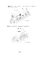
(4) Remove three screws (two "a" and one "b"). (5) Disconnect the long heater wire (of the heater harness) from the upper center of the heat-fixing unit. (6) Disconnect the short heater wire (of the heater harness) from the left end of the heat-fixing unit. (7) Lift up the heat-fixing unit and disconnect the heater thermistor harness from the engine PCB. Heat-fixing unit Iii 0 V Heater thermistor harness Long heater wire , rcl 0 0 4i Short heater wire 0 Latch Engine PCB O • 0 0 (Front) "a": Stepped screw "b": Taptite, cup S M3x8 IV - 38
-
 1
1 -
2
-
3
-
4
-
5
-
6
-
7
-
8
-
9
-
10
-
11
-
12
-
13
-
14
-
15
-
16
-
17
-
18
-
19
-
20
-
21
-
22
-
23
-
24
-
25
-
26
-
27
-
28
-
29
-
30
-
31
-
32
-
33
-
34
-
35
-
36
-
37
-
38
-
39
-
40
-
41
-
42
-
43
-
44
-
45
-
46
-
47
-
48
-
49
-
50
-
51
-
52
-
53
-
54
-
55
-
56
-
57
-
58
-
59
-
60
-
61
-
62
-
63
-
64
-
65
-
66
-
67
-
68
-
69
-
70
-
71
-
72
-
73
-
74
-
75
-
76
-
 77
77 -
 78
78 -
 79
79 -
 80
80 -
 81
81 -
 82
82 -
 83
83 -
 84
84 -
 85
85 -
 86
86 -
 87
87 -
88
-
89
-
90
-
91
-
92
-
93
-
94
-
95
-
96
-
97
-
98
-
99
-
100
-
101
-
102
-
103
-
104
-
105
-
106
-
107
-
108
-
109
-
110
-
111
-
112
-
113
-
114
-
115
-
116
-
117
-
118
-
119
-
120
-
121
-
122
-
123
-
124
-
125
-
126
-
127
-
128
-
129
-
130
-
131
-
132
-
133
-
134
-
135
-
136
-
137
-
138
-
139
-
140
-
141
-
142
-
143
-
144
-
145
-
146
-
147
-
148
-
149
-
150
-
151
-
152
-
153
-
154
-
155
-
156
-
157
-
158
-
159
-
160
-
161
-
162
-
163
-
164
-
165
-
166
-
167
-
168
-
169
-
170
-
171
-
172
-
173
-
174
-
175
-
176
-
177
-
178
-
179
-
180
-
181
-
182
-
183
-
184
-
185
-
186
-
187
-
188
-
189
-
190
-
191
-
192
-
193
-
194
-
195
-
196
-
197
-
198
-
199
-
200
-
201
-
202
-
203
-
204
-
205
-
206
-
207
-
208
-
209
-
210
-
211
-
212
-
213
-
214
-
215
-
216
-
217
-
218
-
219
-
220
-
221
-
222
-
223
-
224
-
225
-
226
-
227
-
228
-
229
 |
 |

(4)
Remove
three
screws
(two
"a"
and
one
"b").
(5)
Disconnect
the
long
heater
wire
(of
the
heater
harness)
from
the
upper
center
of
the
heat
-fixing
unit.
(6)
Disconnect
the
short
heater
wire
(of
the
heater
harness)
from
the
left
end
of
the
heat
-fixing
unit.
(7)
Lift
up
the
heat
-fixing
unit
and
disconnect
the
heater
thermistor
harness
from
the
engine
PCB.
V
Heat
-fixing
unit
Iii
0
Heater
thermistor
harness
Long
heater
wire
r
c
l
4i
Short
heater
wire
,
Latch
0
0
0
Engine
PCB
IV
-
38
O
•
(Front)
0
0
"a":
Stepped
screw
"b":
Taptite,
cup
S
M3x8