Brother International DCP-1400 Service Manual - Page 71
Scanner, Mount, Remove, screws, front, cover, remove, scanner, mount, upwards, direction, arrows,
 |
View all Brother International DCP-1400 manuals
Add to My Manuals
Save this manual to your list of manuals |
Page 71 highlights
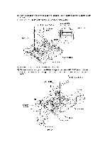
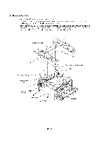
1.10 Scanner Mount (1) Remove two screws "a." (2) Open the front cover and remove two screws "b." (3) Pull the tabs of the scanner mount to the front and upwards (in the direction of arrows CI) to release them from the bosses provided on the main cover. (4) Lift up the scanner mount in the direction of arrow M. "a": Stepped screw (Tightening torque: 0.78 N•m) "b": Taptite, cup S M3x10 (Tightening torque: 0.78 N•m) a" v "a" Scanner mount Tab Tab "b" . Chassis grounding wire Main-relay (motors) harness Main cover Main-relay (CCD) harness o N Main-relay (panel) harness Boss Boss Front cover IV - 27
-
 1
1 -
2
-
3
-
4
-
5
-
6
-
7
-
8
-
9
-
10
-
11
-
12
-
13
-
14
-
15
-
16
-
17
-
18
-
19
-
20
-
21
-
22
-
23
-
24
-
25
-
26
-
27
-
28
-
29
-
30
-
31
-
32
-
33
-
34
-
35
-
36
-
37
-
38
-
39
-
40
-
41
-
42
-
43
-
44
-
45
-
46
-
47
-
48
-
49
-
50
-
51
-
52
-
53
-
54
-
55
-
56
-
57
-
58
-
59
-
60
-
61
-
62
-
63
-
64
-
65
-
 66
66 -
 67
67 -
 68
68 -
 69
69 -
 70
70 -
 71
71 -
 72
72 -
 73
73 -
 74
74 -
 75
75 -
 76
76 -
77
-
78
-
79
-
80
-
81
-
82
-
83
-
84
-
85
-
86
-
87
-
88
-
89
-
90
-
91
-
92
-
93
-
94
-
95
-
96
-
97
-
98
-
99
-
100
-
101
-
102
-
103
-
104
-
105
-
106
-
107
-
108
-
109
-
110
-
111
-
112
-
113
-
114
-
115
-
116
-
117
-
118
-
119
-
120
-
121
-
122
-
123
-
124
-
125
-
126
-
127
-
128
-
129
-
130
-
131
-
132
-
133
-
134
-
135
-
136
-
137
-
138
-
139
-
140
-
141
-
142
-
143
-
144
-
145
-
146
-
147
-
148
-
149
-
150
-
151
-
152
-
153
-
154
-
155
-
156
-
157
-
158
-
159
-
160
-
161
-
162
-
163
-
164
-
165
-
166
-
167
-
168
-
169
-
170
-
171
-
172
-
173
-
174
-
175
-
176
-
177
-
178
-
179
-
180
-
181
-
182
-
183
-
184
-
185
-
186
-
187
-
188
-
189
-
190
-
191
-
192
-
193
-
194
-
195
-
196
-
197
-
198
-
199
-
200
-
201
-
202
-
203
-
204
-
205
-
206
-
207
-
208
-
209
-
210
-
211
-
212
-
213
-
214
-
215
-
216
-
217
-
218
-
219
-
220
-
221
-
222
-
223
-
224
-
225
-
226
-
227
-
228
-
229
 |
 |

1.10
Scanner
Mount
(1)
Remove
two
screws
"a."
(2)
Open
the
front
cover
and
remove
two
screws
"b."
(3)
Pull
the
tabs
of
the
scanner
mount
to
the
front
and
upwards
(in
the
direction
of
arrows
CI)
to
release
them
from
the
bosses
provided
on
the
main
cover.
(4)
Lift
up
the
scanner
mount
in
the
direction
of
arrow
M.
"a":
Stepped
screw
(Tightening
torque:
0.78
N•m)
"b":
Taptite,
cup
S
M3x10
(Tightening
torque:
0.78
N•m)
Tab
.
Chassis
grounding
wire
Main
-relay
(motors)
harness
Main
cover
Main
-relay
(CCD)
harness
a"
Boss
o
IV
-
27
v
"a"
"b"
........
-.
..
N
,
Front
cover
Scanner
mount
Tab
Main
-relay
(panel)
harness
Boss