Brother International DCP-1400 Service Manual - Page 109
Reassembling, Notes
 |
View all Brother International DCP-1400 manuals
Add to My Manuals
Save this manual to your list of manuals |
Page 109 highlights
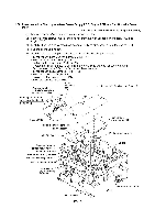
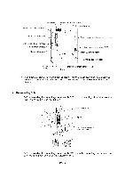
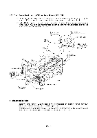
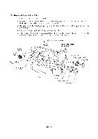
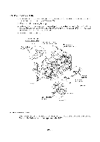
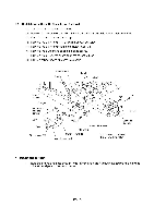
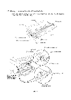
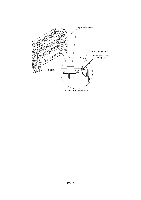
1.25 Toner Sensor (light-receiver) PCB and Toner Sensor (LED) PCB (1) At the right-hand plate of the main chassis, remove the screw from the toner sensor (lightreceiver) PCB, release its harness from the two harness latches, and then pull it out. (2) At the left-hand plate of the main chassis, press the both sides of the lens support on the toner sensor (LED) PCB with your fingers to release them from the main chassis, release its harness from the two latches, and then pull it out. Toner sensor (light-receiver) PCB Main chassis Toner sensor (light-receiver) harness Harness latches Hole provided in the right-hand plate of the main chassis Toner sensor (light-receiver) PCB 666 Harness latch Square hole provided in the left-hand plate a 0 I o of the main 9, ', chassis o Cover sensor Toner sensor (LED) PCB bow •tom 0 O O Lens support (Front) Harness latch ■ Reassembling Notes • Route the toner sensor (LED) harness on the left-hand side of the main chassis as shown above. Also refer to the illustration given on page IV-63. • Route the toner sensor (light-receiver) harness on the right-hand side of the main chassis as shown above and on the top of the plastic frame as shown on page IV-63. IV - 65
-
 1
1 -
2
-
3
-
4
-
5
-
6
-
7
-
8
-
9
-
10
-
11
-
12
-
13
-
14
-
15
-
16
-
17
-
18
-
19
-
20
-
21
-
22
-
23
-
24
-
25
-
26
-
27
-
28
-
29
-
30
-
31
-
32
-
33
-
34
-
35
-
36
-
37
-
38
-
39
-
40
-
41
-
42
-
43
-
44
-
45
-
46
-
47
-
48
-
49
-
50
-
51
-
52
-
53
-
54
-
55
-
56
-
57
-
58
-
59
-
60
-
61
-
62
-
63
-
64
-
65
-
66
-
67
-
68
-
69
-
70
-
71
-
72
-
73
-
74
-
75
-
76
-
77
-
78
-
79
-
80
-
81
-
82
-
83
-
84
-
85
-
86
-
87
-
88
-
89
-
90
-
91
-
92
-
93
-
94
-
95
-
96
-
97
-
98
-
99
-
100
-
101
-
102
-
103
-
 104
104 -
 105
105 -
 106
106 -
 107
107 -
 108
108 -
 109
109 -
 110
110 -
 111
111 -
 112
112 -
 113
113 -
 114
114 -
115
-
116
-
117
-
118
-
119
-
120
-
121
-
122
-
123
-
124
-
125
-
126
-
127
-
128
-
129
-
130
-
131
-
132
-
133
-
134
-
135
-
136
-
137
-
138
-
139
-
140
-
141
-
142
-
143
-
144
-
145
-
146
-
147
-
148
-
149
-
150
-
151
-
152
-
153
-
154
-
155
-
156
-
157
-
158
-
159
-
160
-
161
-
162
-
163
-
164
-
165
-
166
-
167
-
168
-
169
-
170
-
171
-
172
-
173
-
174
-
175
-
176
-
177
-
178
-
179
-
180
-
181
-
182
-
183
-
184
-
185
-
186
-
187
-
188
-
189
-
190
-
191
-
192
-
193
-
194
-
195
-
196
-
197
-
198
-
199
-
200
-
201
-
202
-
203
-
204
-
205
-
206
-
207
-
208
-
209
-
210
-
211
-
212
-
213
-
214
-
215
-
216
-
217
-
218
-
219
-
220
-
221
-
222
-
223
-
224
-
225
-
226
-
227
-
228
-
229
 |
 |
