Brother International DCP-1400 Service Manual - Page 110
disassembly
 |
View all Brother International DCP-1400 manuals
Add to My Manuals
Save this manual to your list of manuals |
Page 110 highlights
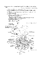
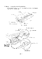
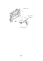
1.26 Gears and Paper Pick-up Roller (1) Place the main chassis upside down. (2) Remove the inner gear 54 (by pulling its pawl outwards), gear 45 set P/R, gear 20 P/R, and the bushing from the end of the paper pick-up roller shaft. (3) Remove the pawled bushing by pulling its pawl outwards, then remove the paper pick-up roller and its shaft. (4) Remove the gear 40/54, gear 45 set FIR, and gear 20 FIR. (5) If the engine PCB has been removed, take out the cassette sensor actuator. (This prevents the actuator from dropping during the following disassembly jobs.) Pawled bushing Cassette sensor actuator / Main chassis placed upside down. Paper pick-up roller Paper pick-up roller shaft Gear 20 F/R Gear 45 set F/R / Gear 40/54 Itv (Front) Bushing' Gear 20 P/R Gear 45 set P/R Inner gear 54 IV - 66
-
 1
1 -
2
-
3
-
4
-
5
-
6
-
7
-
8
-
9
-
10
-
11
-
12
-
13
-
14
-
15
-
16
-
17
-
18
-
19
-
20
-
21
-
22
-
23
-
24
-
25
-
26
-
27
-
28
-
29
-
30
-
31
-
32
-
33
-
34
-
35
-
36
-
37
-
38
-
39
-
40
-
41
-
42
-
43
-
44
-
45
-
46
-
47
-
48
-
49
-
50
-
51
-
52
-
53
-
54
-
55
-
56
-
57
-
58
-
59
-
60
-
61
-
62
-
63
-
64
-
65
-
66
-
67
-
68
-
69
-
70
-
71
-
72
-
73
-
74
-
75
-
76
-
77
-
78
-
79
-
80
-
81
-
82
-
83
-
84
-
85
-
86
-
87
-
88
-
89
-
90
-
91
-
92
-
93
-
94
-
95
-
96
-
97
-
98
-
99
-
100
-
101
-
102
-
103
-
104
-
 105
105 -
 106
106 -
 107
107 -
 108
108 -
 109
109 -
 110
110 -
 111
111 -
 112
112 -
 113
113 -
 114
114 -
 115
115 -
116
-
117
-
118
-
119
-
120
-
121
-
122
-
123
-
124
-
125
-
126
-
127
-
128
-
129
-
130
-
131
-
132
-
133
-
134
-
135
-
136
-
137
-
138
-
139
-
140
-
141
-
142
-
143
-
144
-
145
-
146
-
147
-
148
-
149
-
150
-
151
-
152
-
153
-
154
-
155
-
156
-
157
-
158
-
159
-
160
-
161
-
162
-
163
-
164
-
165
-
166
-
167
-
168
-
169
-
170
-
171
-
172
-
173
-
174
-
175
-
176
-
177
-
178
-
179
-
180
-
181
-
182
-
183
-
184
-
185
-
186
-
187
-
188
-
189
-
190
-
191
-
192
-
193
-
194
-
195
-
196
-
197
-
198
-
199
-
200
-
201
-
202
-
203
-
204
-
205
-
206
-
207
-
208
-
209
-
210
-
211
-
212
-
213
-
214
-
215
-
216
-
217
-
218
-
219
-
220
-
221
-
222
-
223
-
224
-
225
-
226
-
227
-
228
-
229
 |
 |
