Brother International DCP-1400 Service Manual - Page 63
Disassembling
 |
View all Brother International DCP-1400 manuals
Add to My Manuals
Save this manual to your list of manuals |
Page 63 highlights
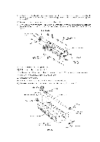
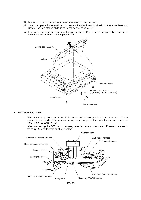
• When connecting the CCD motor harness, panel harness, and scanner HP sensor harness to the relay PCB, route them as shown below. CCD flat cable (turned up) Ferrite core TT Scanner HP sensor harness Panel harness Black film Scanner base Cutout provided in the black film Viewed from the bottom [ Disassembling the Scanner Unit ] The disassembling job of the scanner unit should be done in a clean room to prevent dust or dirt from getting into the scanner unit. 1) Remove the four screws from the scanner top cover. 2) Separate the scanner top cover from the scanner base. Taptite, cup B M4x12 .. H Scanner top cover ? Gear 17/97 . IV - 19 Scanner base Panel harness
-
 1
1 -
2
-
3
-
4
-
5
-
6
-
7
-
8
-
9
-
10
-
11
-
12
-
13
-
14
-
15
-
16
-
17
-
18
-
19
-
20
-
21
-
22
-
23
-
24
-
25
-
26
-
27
-
28
-
29
-
30
-
31
-
32
-
33
-
34
-
35
-
36
-
37
-
38
-
39
-
40
-
41
-
42
-
43
-
44
-
45
-
46
-
47
-
48
-
49
-
50
-
51
-
52
-
53
-
54
-
55
-
56
-
57
-
 58
58 -
 59
59 -
 60
60 -
 61
61 -
 62
62 -
 63
63 -
 64
64 -
 65
65 -
 66
66 -
 67
67 -
 68
68 -
69
-
70
-
71
-
72
-
73
-
74
-
75
-
76
-
77
-
78
-
79
-
80
-
81
-
82
-
83
-
84
-
85
-
86
-
87
-
88
-
89
-
90
-
91
-
92
-
93
-
94
-
95
-
96
-
97
-
98
-
99
-
100
-
101
-
102
-
103
-
104
-
105
-
106
-
107
-
108
-
109
-
110
-
111
-
112
-
113
-
114
-
115
-
116
-
117
-
118
-
119
-
120
-
121
-
122
-
123
-
124
-
125
-
126
-
127
-
128
-
129
-
130
-
131
-
132
-
133
-
134
-
135
-
136
-
137
-
138
-
139
-
140
-
141
-
142
-
143
-
144
-
145
-
146
-
147
-
148
-
149
-
150
-
151
-
152
-
153
-
154
-
155
-
156
-
157
-
158
-
159
-
160
-
161
-
162
-
163
-
164
-
165
-
166
-
167
-
168
-
169
-
170
-
171
-
172
-
173
-
174
-
175
-
176
-
177
-
178
-
179
-
180
-
181
-
182
-
183
-
184
-
185
-
186
-
187
-
188
-
189
-
190
-
191
-
192
-
193
-
194
-
195
-
196
-
197
-
198
-
199
-
200
-
201
-
202
-
203
-
204
-
205
-
206
-
207
-
208
-
209
-
210
-
211
-
212
-
213
-
214
-
215
-
216
-
217
-
218
-
219
-
220
-
221
-
222
-
223
-
224
-
225
-
226
-
227
-
228
-
229
 |
 |

•
When
connecting
the
CCD
motor
harness,
panel
harness,
and
scanner
HP
sensor
harness
to
the
relay
PCB,
route
them
as
shown
below.
CCD
flat
cable
(turned
up)
Ferrite
core
Black
film
TT
Viewed
from
the
bottom
Scanner
HP
sensor
harness
Panel
harness
Scanner
base
Cutout
provided
in
the
black
film
[
Disassembling
the
Scanner
Unit
]
The
disassembling
job
of
the
scanner
unit
should
be
done
in
a
clean
room
to
prevent
dust
or
dirt
from
getting
into
the
scanner
unit.
1)
Remove
the
four
screws
from
the
scanner
top
cover.
2)
Separate
the
scanner
top
cover
from
the
scanner
base.
Taptite,
cup
B
M4x12
Gear
17/97
H
IV
-
19
Scanner
top
cover
..
?
.
Scanner
base
Panel
harness