Brother International DCP-1400 Service Manual - Page 53
Brother International DCP-1400 Manual
 |
View all Brother International DCP-1400 manuals
Add to My Manuals
Save this manual to your list of manuals |
Page 53 highlights
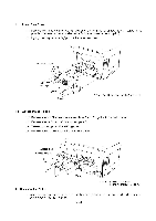
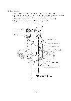
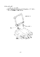
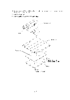
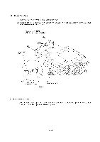
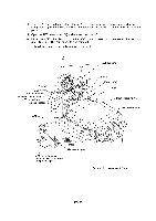
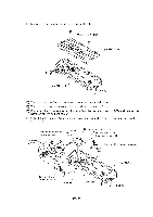
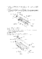
1.6 ADF Unit (1) Remove screw "a" from the harness support. (2) Remove screw "b" to release the grounding wires. (3) Disconnect the following from the relay PCB: • CCD flat cable (P4) • ADF motor harness (4-pin, P3) • Document sensor harness (4-pin, P8) Scanner top cover "a" Harness support CCD flat cable Document sensor harness "b" ADF motor harness (Rear) Relay PCB Chassis grounding wire ADF grounding wire Scanner grounding wire "a": Taptite, cup B M3x8 "b": Taptite, cup S M3x6 IV - 9
-
 1
1 -
2
-
3
-
4
-
5
-
6
-
7
-
8
-
9
-
10
-
11
-
12
-
13
-
14
-
15
-
16
-
17
-
18
-
19
-
20
-
21
-
22
-
23
-
24
-
25
-
26
-
27
-
28
-
29
-
30
-
31
-
32
-
33
-
34
-
35
-
36
-
37
-
38
-
39
-
40
-
41
-
42
-
43
-
44
-
45
-
46
-
47
-
 48
48 -
 49
49 -
 50
50 -
 51
51 -
 52
52 -
 53
53 -
 54
54 -
 55
55 -
 56
56 -
 57
57 -
 58
58 -
59
-
60
-
61
-
62
-
63
-
64
-
65
-
66
-
67
-
68
-
69
-
70
-
71
-
72
-
73
-
74
-
75
-
76
-
77
-
78
-
79
-
80
-
81
-
82
-
83
-
84
-
85
-
86
-
87
-
88
-
89
-
90
-
91
-
92
-
93
-
94
-
95
-
96
-
97
-
98
-
99
-
100
-
101
-
102
-
103
-
104
-
105
-
106
-
107
-
108
-
109
-
110
-
111
-
112
-
113
-
114
-
115
-
116
-
117
-
118
-
119
-
120
-
121
-
122
-
123
-
124
-
125
-
126
-
127
-
128
-
129
-
130
-
131
-
132
-
133
-
134
-
135
-
136
-
137
-
138
-
139
-
140
-
141
-
142
-
143
-
144
-
145
-
146
-
147
-
148
-
149
-
150
-
151
-
152
-
153
-
154
-
155
-
156
-
157
-
158
-
159
-
160
-
161
-
162
-
163
-
164
-
165
-
166
-
167
-
168
-
169
-
170
-
171
-
172
-
173
-
174
-
175
-
176
-
177
-
178
-
179
-
180
-
181
-
182
-
183
-
184
-
185
-
186
-
187
-
188
-
189
-
190
-
191
-
192
-
193
-
194
-
195
-
196
-
197
-
198
-
199
-
200
-
201
-
202
-
203
-
204
-
205
-
206
-
207
-
208
-
209
-
210
-
211
-
212
-
213
-
214
-
215
-
216
-
217
-
218
-
219
-
220
-
221
-
222
-
223
-
224
-
225
-
226
-
227
-
228
-
229
 |
 |

1.6
ADF
Unit
(1)
Remove
screw
"a"
from
the
harness
support.
(2)
Remove
screw
"b"
to
release
the
grounding
wires.
(3)
Disconnect
the
following
from
the
relay
PCB:
•
CCD
flat
cable
(P4)
•
ADF
motor
harness
(4
-pin,
P3)
•
Document
sensor
harness
(4
-pin,
P8)
Scanner
top
cover
"a"
Harness
support
CCD
flat
cable
Document
sensor
harness
ADF
motor
harness
(Rear)
"b"
IV
-
9
Relay
PCB
Chassis
grounding
wire
ADF
grounding
wire
Scanner
grounding
wire
"a":
Taptite,
cup
B
M3x8
"b":
Taptite,
cup
S
M3x6