Brother International Innov-is XJ2 Operation Manual - Page 11
Getting Ready
 |
View all Brother International Innov-is XJ2 manuals
Add to My Manuals
Save this manual to your list of manuals |
Page 11 highlights
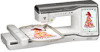
NAMES OF MACHINE PARTS 1 Chapter GETTING READY Note • Be sure to install the latest software. Refer to "UPDATING YOUR MACHINE'S SOFTWARE" on page 196. NAMES OF MACHINE PARTS Main Parts a bc de f g o C Flat bed attachment with accessory compartment (page 11) D Thread cutter (page 38) E Thread guide plate (page 33) F Connector for the presser foot (page 46, page 104) G Handle Carry the machine by its handle when transporting the machine. H Presser foot lever You cannot use the presser foot lever after the presser foot has been raised using (Presser foot lifter button). I Air vent The air vent allows the air surrounding the motor to circulate. Do not cover the air vent while the machine is being used. J Main power switch (page 14) K Foot controller (page 51) L Power cord receptacle (page 14) M Foot controller jack (page 51) N USB port for mouse (page 30) O USB port P Handwheel Turn the handwheel toward you (counterclockwise) to raise and lower the needle. GETTING READY 1 n Needle and Presser Foot Section ih m l k j p q r y x w v s t u 1 Top cover 2 Pretension disk (page 32) 3 Thread guide for bobbin winding (page 31) 4 Spool pin (page 37) 5 Spool cap (page 30) 6 Supplemental spool pin (page 30) 7 Bobbin winder (page 30) 8 LCD (liquid crystal display) (page 16) 9 Speaker 0 Knee lifter (page 62) A Knee lifter slot (page 62) B Operation buttons and sewing speed controller (page 10) a b c j i d e h f g 1 Buttonhole lever (page 84) 2 Presser foot holder screw (page 45, page 103) 3 Presser foot holder (page 45) 4 Presser foot locking pin (page 65) 5 Presser foot The presser foot consistently applies pressure to the fabric as sewing takes place. Attach the appropriate presser foot for the selected stitch. 6 Feed dogs The feed dogs feed the fabric in the sewing direction. 7 Bobbin cover (page 34) 8 Needle plate (page 68) 9 Needle bar thread guide (page 37) 0 Needle clamp screw (page 43) 9
-
 1
1 -
2
-
3
-
4
-
5
-
 6
6 -
 7
7 -
 8
8 -
 9
9 -
 10
10 -
 11
11 -
 12
12 -
 13
13 -
 14
14 -
 15
15 -
 16
16 -
17
-
18
-
19
-
20
-
21
-
22
-
23
-
24
-
25
-
26
-
27
-
28
-
29
-
30
-
31
-
32
-
33
-
34
-
35
-
36
-
37
-
38
-
39
-
40
-
41
-
42
-
43
-
44
-
45
-
46
-
47
-
48
-
49
-
50
-
51
-
52
-
53
-
54
-
55
-
56
-
57
-
58
-
59
-
60
-
61
-
62
-
63
-
64
-
65
-
66
-
67
-
68
-
69
-
70
-
71
-
72
-
73
-
74
-
75
-
76
-
77
-
78
-
79
-
80
-
81
-
82
-
83
-
84
-
85
-
86
-
87
-
88
-
89
-
90
-
91
-
92
-
93
-
94
-
95
-
96
-
97
-
98
-
99
-
100
-
101
-
102
-
103
-
104
-
105
-
106
-
107
-
108
-
109
-
110
-
111
-
112
-
113
-
114
-
115
-
116
-
117
-
118
-
119
-
120
-
121
-
122
-
123
-
124
-
125
-
126
-
127
-
128
-
129
-
130
-
131
-
132
-
133
-
134
-
135
-
136
-
137
-
138
-
139
-
140
-
141
-
142
-
143
-
144
-
145
-
146
-
147
-
148
-
149
-
150
-
151
-
152
-
153
-
154
-
155
-
156
-
157
-
158
-
159
-
160
-
161
-
162
-
163
-
164
-
165
-
166
-
167
-
168
-
169
-
170
-
171
-
172
-
173
-
174
-
175
-
176
-
177
-
178
-
179
-
180
-
181
-
182
-
183
-
184
-
185
-
186
-
187
-
188
-
189
-
190
-
191
-
192
-
193
-
194
-
195
-
196
-
197
-
198
-
199
-
200
-
201
-
202
-
203
-
204
-
205
-
206
-
207
-
208
-
209
-
210
-
211
-
212
 |
 |
