Fluke 125 Fluke 125 Users Manual - Page 21
Looking at the Measurement, Connections, Input
 |
View all Fluke 125 manuals
Add to My Manuals
Save this manual to your list of manuals |
Page 21 highlights
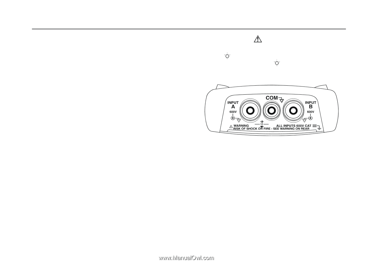
Looking at the Measurement Connections Look at the top of the test tool. The test tool provides two 4-mm safety shielded banana jack inputs (red input A and gray input B) and a black safety 4-mm banana jack input (COM). (See Figure 1-3.) Input A You can always use the red input A for all single input measurements possible with the test tool. Input B For measurements on two different signals you can use the gray input B together with the red input A . COM You can use the black COMmon as single ground for low frequency measurements, and for Continuity, Ohm (Ω), Diode, and Capacitance measurements. 1 General Operating Instructions Looking at the Measurement Connections Warning To avoid electrical shock or fire, use only one COM (common) connection, or ensure that all connections to COM are at the same potential. Figure 1-3. Measurement Connections 1-5
-
 1
1 -
2
-
3
-
4
-
5
-
6
-
7
-
8
-
9
-
10
-
11
-
12
-
13
-
14
-
15
-
 16
16 -
 17
17 -
 18
18 -
 19
19 -
 20
20 -
 21
21 -
 22
22 -
 23
23 -
 24
24 -
 25
25 -
 26
26 -
27
-
28
-
29
-
30
-
31
-
32
-
33
-
34
-
35
-
36
-
37
-
38
-
39
-
40
-
41
-
42
-
43
-
44
-
45
-
46
-
47
-
48
-
49
-
50
-
51
-
52
-
53
-
54
-
55
-
56
-
57
-
58
-
59
-
60
-
61
-
62
-
63
-
64
-
65
-
66
-
67
-
68
-
69
-
70
-
71
-
72
-
73
-
74
-
75
-
76
-
77
-
78
-
79
-
80
-
81
-
82
-
83
-
84
-
85
-
86
-
87
-
88
-
89
-
90
-
91
-
92
-
93
-
94
-
95
-
96
-
97
-
98
-
99
-
100
-
101
-
102
-
103
-
104
-
105
-
106
-
107
-
108
-
109
-
110
-
111
-
112
-
113
 |
 |