Fluke 125 Fluke 125 Users Manual - Page 26
Making Measurements, Connecting the Inputs
 |
View all Fluke 125 manuals
Add to My Manuals
Save this manual to your list of manuals |
Page 26 highlights
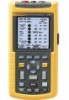
Fluke 125 Users Manual Making Measurements The reading area displays the numeric readings of the chosen measurements on the waveform that is applied to the input jack. Connecting the Inputs Voltage measurements See figure 2-3. For proper grounding connect the short ground leads d to the same ground potential. You can also use test lead c for grounding. See also Using Proper Grounding in chapter 9. Ohm (Ω), continuity, diode, and capacitance measurements See figure 2-4. Use the red shielded test lead from input A and the black unshielded ground lead from COM (common). Current measurements See figure 2-5. Select the probe setting that matches the used current clamp and its setting (e.g. 1 mV/A), see Chapter 1, Measurement Probes and Settings. Temperature measurements See figure 2-6. Use a 1 mV/°C or 1 mV/°F temperature transmitter to get the correct temperature reading. Power measurements See figure 2-7. Select correct probe settings for voltage measurement on input A, and current measurement on input B. 2 1 2 Figure 2-3. Volts Measurement Setup 2-4
-
 1
1 -
2
-
3
-
4
-
5
-
6
-
7
-
8
-
9
-
10
-
11
-
12
-
13
-
14
-
15
-
16
-
17
-
18
-
19
-
20
-
 21
21 -
 22
22 -
 23
23 -
 24
24 -
 25
25 -
 26
26 -
 27
27 -
 28
28 -
 29
29 -
 30
30 -
 31
31 -
32
-
33
-
34
-
35
-
36
-
37
-
38
-
39
-
40
-
41
-
42
-
43
-
44
-
45
-
46
-
47
-
48
-
49
-
50
-
51
-
52
-
53
-
54
-
55
-
56
-
57
-
58
-
59
-
60
-
61
-
62
-
63
-
64
-
65
-
66
-
67
-
68
-
69
-
70
-
71
-
72
-
73
-
74
-
75
-
76
-
77
-
78
-
79
-
80
-
81
-
82
-
83
-
84
-
85
-
86
-
87
-
88
-
89
-
90
-
91
-
92
-
93
-
94
-
95
-
96
-
97
-
98
-
99
-
100
-
101
-
102
-
103
-
104
-
105
-
106
-
107
-
108
-
109
-
110
-
111
-
112
-
113
 |
 |
