Fluke 125 Fluke 125 Users Manual - Page 47
Using the 10:1 Probe for High Frequency, Measurements., Probe Attenuation., Probe Adjustment.
 |
View all Fluke 125 manuals
Add to My Manuals
Save this manual to your list of manuals |
Page 47 highlights
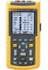
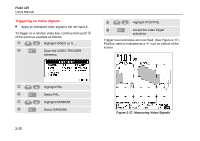
2 Scope/Meter Mode Using the 10:1 Probe for High Frequency Measurements. Using the 10:1 Probe for High Frequency Measurements. The test tool is supplied with a model VP40 10:1 Probe. Use of this Probe is recommended when you measure high frequency signals in circuits with a high impedance. The loading of the circuit by a 10:1 Probe is much lower than that of a 1:1 Shielded Test Lead. Probe attenuation and probe adjustment must be observed when using a 10:1 Probe. Probe Attenuation. The Probe attenuates the signal 10 times. Proceed as follows to adapt the Test Tool's voltage readout to this attenuation. The example below is for a Probe connected to input A: c The Input A MEASUREMENTS menu and a F1....F4 button bar pops up. d Open the INPUT... menu e Highlight PROBE: SELECT... f Open the PROBE on A menu g Highlight 10:1 V h Accept the probe type. The menu will be closed. Observe that the 10 times attenuation of the Probe is compensated in the voltage readout. Probe Adjustment. The Probe of model VP40 such as supplied with the Test Tool is always adapted correctly to its inputs: high frequency adjustment is not necessary. Other 10:1 Probes however must be adjusted for optimal High Frequency performance. How to adjust these Probes is explained in Chapter 8 under 'Using and Adjusting 10:1 Scope Probes'. 2-25
-
 1
1 -
2
-
3
-
4
-
5
-
6
-
7
-
8
-
9
-
10
-
11
-
12
-
13
-
14
-
15
-
16
-
17
-
18
-
19
-
20
-
21
-
22
-
23
-
24
-
25
-
26
-
27
-
28
-
29
-
30
-
31
-
32
-
33
-
34
-
35
-
36
-
37
-
38
-
39
-
40
-
41
-
 42
42 -
 43
43 -
 44
44 -
 45
45 -
 46
46 -
 47
47 -
 48
48 -
 49
49 -
 50
50 -
 51
51 -
 52
52 -
53
-
54
-
55
-
56
-
57
-
58
-
59
-
60
-
61
-
62
-
63
-
64
-
65
-
66
-
67
-
68
-
69
-
70
-
71
-
72
-
73
-
74
-
75
-
76
-
77
-
78
-
79
-
80
-
81
-
82
-
83
-
84
-
85
-
86
-
87
-
88
-
89
-
90
-
91
-
92
-
93
-
94
-
95
-
96
-
97
-
98
-
99
-
100
-
101
-
102
-
103
-
104
-
105
-
106
-
107
-
108
-
109
-
110
-
111
-
112
-
113
 |
 |
