Fluke 125 Fluke 125 Users Manual - Page 33
Positioning the Waveform on the Screen, Positioning the Waveform
 |
View all Fluke 125 manuals
Add to My Manuals
Save this manual to your list of manuals |
Page 33 highlights
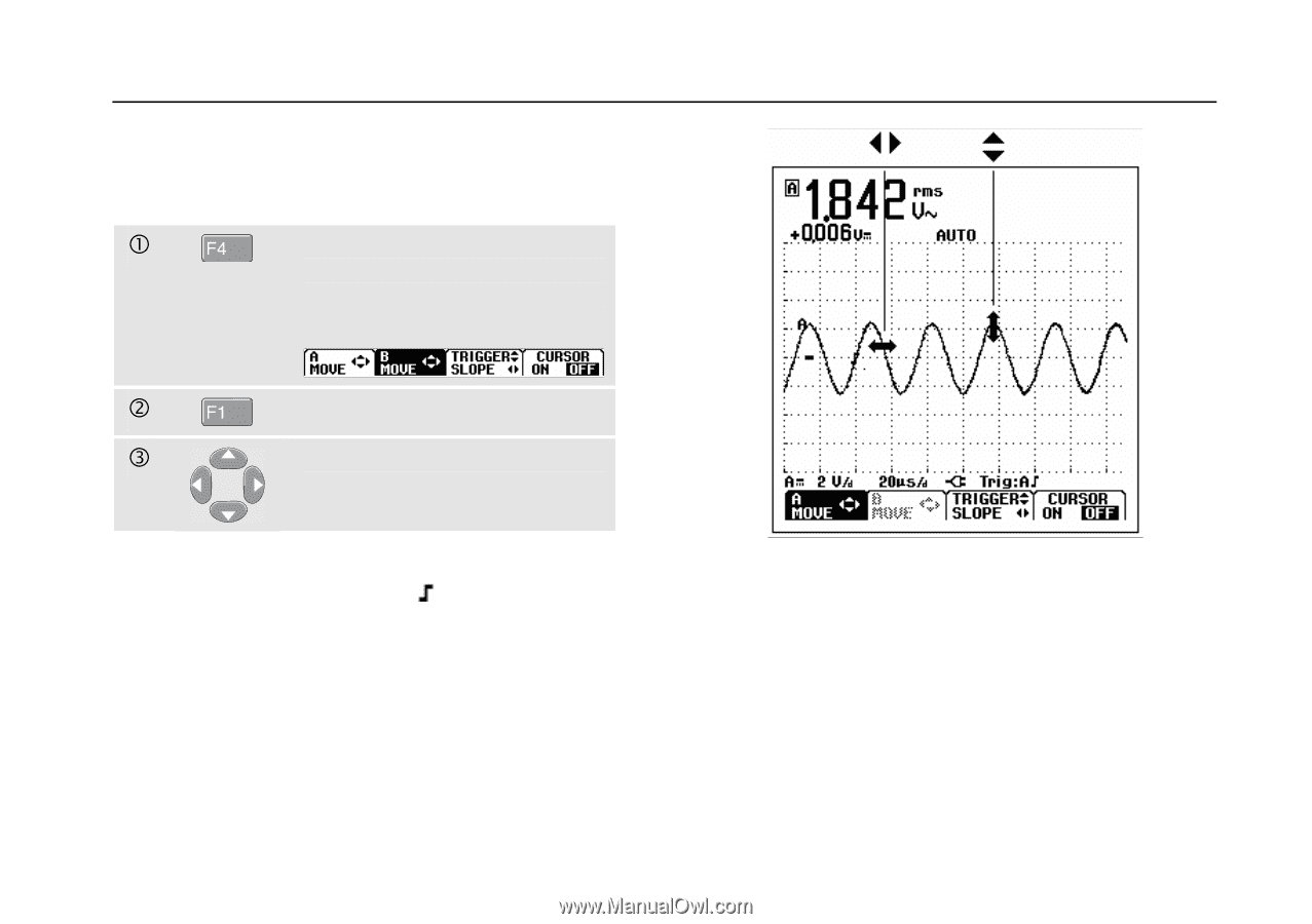
Positioning the Waveform on the Screen Considerable flexibility is offered in moving the waveform(s) around the screen. c Press until you have left any open menu. Observe that the following main menu appears on bottom of the screen. d Choose A MOVE e Position the waveform of INPUT A on the screen. Waveform positioning is demonstrated in Figure 2-10. Observe that the trigger identifier ( ) moves horizontally on the screen. Note: For 3 phase power measurements the waveform positions are fixed. 2 Scope/Meter Mode Changing the Graphic Representation on the Screen Figure 2-10. Positioning the Waveform 2-11
-
 1
1 -
2
-
3
-
4
-
5
-
6
-
7
-
8
-
9
-
10
-
11
-
12
-
13
-
14
-
15
-
16
-
17
-
18
-
19
-
20
-
21
-
22
-
23
-
24
-
25
-
26
-
27
-
 28
28 -
 29
29 -
 30
30 -
 31
31 -
 32
32 -
 33
33 -
 34
34 -
 35
35 -
 36
36 -
 37
37 -
 38
38 -
39
-
40
-
41
-
42
-
43
-
44
-
45
-
46
-
47
-
48
-
49
-
50
-
51
-
52
-
53
-
54
-
55
-
56
-
57
-
58
-
59
-
60
-
61
-
62
-
63
-
64
-
65
-
66
-
67
-
68
-
69
-
70
-
71
-
72
-
73
-
74
-
75
-
76
-
77
-
78
-
79
-
80
-
81
-
82
-
83
-
84
-
85
-
86
-
87
-
88
-
89
-
90
-
91
-
92
-
93
-
94
-
95
-
96
-
97
-
98
-
99
-
100
-
101
-
102
-
103
-
104
-
105
-
106
-
107
-
108
-
109
-
110
-
111
-
112
-
113
 |
 |
Scope/Meter Mode
Changing the Graphic Representation on the Screen
2
2-11
Positioning the Waveform on the Screen
Considerable flexibility is offered in moving the
waveform(s) around the screen.
Press until you have left any open
menu. Observe that the following
main menu appears on bottom of
the screen.
Choose A MOVE
Position the waveform of INPUT
A on the screen.
Waveform positioning is demonstrated in Figure 2-10.
Observe that the trigger identifier (
) moves horizontally
on the screen.
Note:
For 3 phase power measurements the waveform
positions are fixed.
Figure 2-10. Positioning the Waveform