HP 2700n Service Manual - Page 94
Pickup-and-feed-system, Sensors in the pickup-and-feed system trays (cassettes)
 |
View all HP 2700n manuals
Add to My Manuals
Save this manual to your list of manuals |
Page 94 highlights
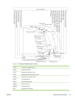
Pickup-and-feed-system The pickup and feed system consists of several types of feed rollers and sensors. The DC controller drives the system by controlling the feed motor (M4), ETB motor (M5), and four drum motors (M6, M7, M8, M9) and the solenoids for the trays. NOTE Tray 2 must be installed in order to print from tray 1 or tray 3. Figure 4-5 Pickup-and-feed system Sensors in the pickup-and-feed system trays (cassettes) Paper sensors detect media in the trays. Other sensors react to the media as it moves through the paper path. If the media does not reach or pass each sensor within a specified time period, the DC controller determines that a jam has occurred and alerts the formatter. 76 Chapter 4 Theory of operation ENWW
-
 1
1 -
2
-
3
-
4
-
5
-
6
-
7
-
8
-
9
-
10
-
11
-
12
-
13
-
14
-
15
-
16
-
17
-
18
-
19
-
20
-
21
-
22
-
23
-
24
-
25
-
26
-
27
-
28
-
29
-
30
-
31
-
32
-
33
-
34
-
35
-
36
-
37
-
38
-
39
-
40
-
41
-
42
-
43
-
44
-
45
-
46
-
47
-
48
-
49
-
50
-
51
-
52
-
53
-
54
-
55
-
56
-
57
-
58
-
59
-
60
-
61
-
62
-
63
-
64
-
65
-
66
-
67
-
68
-
69
-
70
-
71
-
72
-
73
-
74
-
75
-
76
-
77
-
78
-
79
-
80
-
81
-
82
-
83
-
84
-
85
-
86
-
87
-
88
-
 89
89 -
 90
90 -
 91
91 -
 92
92 -
 93
93 -
 94
94 -
 95
95 -
 96
96 -
 97
97 -
 98
98 -
 99
99 -
100
-
101
-
102
-
103
-
104
-
105
-
106
-
107
-
108
-
109
-
110
-
111
-
112
-
113
-
114
-
115
-
116
-
117
-
118
-
119
-
120
-
121
-
122
-
123
-
124
-
125
-
126
-
127
-
128
-
129
-
130
-
131
-
132
-
133
-
134
-
135
-
136
-
137
-
138
-
139
-
140
-
141
-
142
-
143
-
144
-
145
-
146
-
147
-
148
-
149
-
150
-
151
-
152
-
153
-
154
-
155
-
156
-
157
-
158
-
159
-
160
-
161
-
162
-
163
-
164
-
165
-
166
-
167
-
168
-
169
-
170
-
171
-
172
-
173
-
174
-
175
-
176
-
177
-
178
-
179
-
180
-
181
-
182
-
183
-
184
-
185
-
186
-
187
-
188
-
189
-
190
-
191
-
192
-
193
-
194
-
195
-
196
-
197
-
198
-
199
-
200
-
201
-
202
-
203
-
204
-
205
-
206
-
207
-
208
-
209
-
210
-
211
-
212
-
213
-
214
-
215
-
216
-
217
-
218
-
219
-
220
-
221
-
222
-
223
-
224
-
225
-
226
-
227
-
228
-
229
-
230
-
231
-
232
-
233
-
234
-
235
-
236
-
237
-
238
-
239
-
240
-
241
-
242
-
243
-
244
-
245
-
246
-
247
-
248
-
249
-
250
-
251
-
252
-
253
-
254
-
255
-
256
-
257
-
258
-
259
-
260
-
261
-
262
-
263
-
264
-
265
-
266
-
267
-
268
-
269
-
270
-
271
-
272
-
273
-
274
-
275
-
276
-
277
-
278
-
279
-
280
-
281
-
282
-
283
-
284
-
285
-
286
-
287
-
288
-
289
-
290
-
291
-
292
-
293
-
294
-
295
-
296
-
297
-
298
-
299
-
300
-
301
-
302
-
303
-
304
-
305
-
306
-
307
-
308
-
309
-
310
-
311
-
312
-
313
-
314
-
315
-
316
-
317
-
318
-
319
-
320
-
321
-
322
-
323
-
324
-
325
-
326
-
327
-
328
-
329
-
330
-
331
-
332
-
333
-
334
-
335
-
336
-
337
-
338
-
339
-
340
-
341
-
342
-
343
-
344
-
345
-
346
-
347
-
348
 |
 |

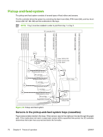
Pickup-and-feed-system
The pickup and feed system consists of several types of feed rollers and sensors.
The DC controller drives the system by controlling the feed motor (M4), ETB motor (M5), and four drum
motors (M6, M7, M8, M9) and the solenoids for the trays.
NOTE
Tray 2 must be installed in order to print from tray 1 or tray 3.
Figure 4-5
Pickup-and-feed system
Sensors in the pickup-and-feed system trays (cassettes)
Paper sensors detect media in the trays. Other sensors react to the media as it moves through the paper
path. If the media does not reach or pass each sensor within a specified time period, the DC controller
determines that a jam has occurred and alerts the formatter.
76
Chapter 4
Theory of operation
ENWW