HP Rp2430 rp24xx A180 User Manual
HP Rp2430 - Server - 650 MHz Manual
 |
View all HP Rp2430 manuals
Add to My Manuals
Save this manual to your list of manuals |
HP Rp2430 manual content summary:
- HP Rp2430 | rp24xx A180 User Manual - Page 1
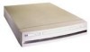
User's Manual HP 9000 Model A-180 Manufacturing Part Number : Z4045-90002 February 2000 - HP Rp2430 | rp24xx A180 User Manual - Page 2
Notice Hewlett-Packard makes no warranty of any kind with regard to this material, including but not limited to, the implied warranties of merchantability and fitness for a particular purpose. Hewlett-Packard shall not be liable for errors contained herein or for incidental or consequential damages - HP Rp2430 | rp24xx A180 User Manual - Page 3
3 - HP Rp2430 | rp24xx A180 User Manual - Page 4
4 - HP Rp2430 | rp24xx A180 User Manual - Page 5
alone System in an HP-supported Cabinet 35 External Connections 38 Installing Internal Add-On Components 41 Installing Memory (RAM) Modules 41 Installing Cache Memory SIMMs 42 Installing Embedded Disk Drives 43 Installing Input/Output (I/O) Cards 46 A-Class Server Power Up and Boot Procedures - HP Rp2430 | rp24xx A180 User Manual - Page 6
Light-Emitting Diode (LED) Interpretation 66 Firmware Warning Messages 72 Chassis Code Summary 73 Troubleshooting the ASCII Console 76 Troubleshooting the Secure Web Console 77 Troubleshooting Embedded Disks 79 Troubleshooting LAN 80 A-Class Server Corrective Action 81 Overview 81 Ordering - HP Rp2430 | rp24xx A180 User Manual - Page 7
Precautions 97 Before You Do Anything 97 Card Load Order Rules 97 I/O Card Removal 98 I/O Card Replacement 99 Replacing an A-Class Server Exchange Base Unit (EBU 100 Overview 100 Electrostatic Discharge Precautions 101 Before You Do Anything 101 Removable Components 102 Move the Components - HP Rp2430 | rp24xx A180 User Manual - Page 8
Contents 8 - HP Rp2430 | rp24xx A180 User Manual - Page 9
A-Class System Overview and Reference 1 A-Class System Overview and Reference Chapter 1 9 - HP Rp2430 | rp24xx A180 User Manual - Page 10
addition to the HP9000 server family, targeted at the ISP server market. The A-Class server design allows the use of existing qualified peripherals and I/O add-in options. It is a PCXL-2 (PA-7300 RISC Processor) based platform designed to support the UNIX Internet Service Provider (ISP) market - HP Rp2430 | rp24xx A180 User Manual - Page 11
Service reference data consists of the following: • 11"x14" maintenance label • A A-Class Server System Block Diagram for maintenance personnel and operators. • The A-Class Server System Regulatory Compliance Statements required by the U. S. government and required by some countries that import HP - HP Rp2430 | rp24xx A180 User Manual - Page 12
A-Class System Overview and Reference A-Class Server System Block Diagram A-Class Server System Block Diagram Overview The A-Class server block diagram is included for information. 12 Chapter 1 - HP Rp2430 | rp24xx A180 User Manual - Page 13
required by some countries for international importation of A-Class servers. The following information is provided: • Regulatory Information Acoustics (Germany) • UK General Approval (United Kingdom only) • Internal Modem and HP A2991-600xx Line Access Module (LAM) • Terminal DOC (Canada only) • - HP Rp2430 | rp24xx A180 User Manual - Page 14
to earth according to IEC 950). Locate the AC outlet near the computer! The ac power cord is this product's main ac disconnect device and must be easily accessible at all times. Battery Notice This product contains a Lithium battery. This battery is not to be removed or replaced by the user. If the - HP Rp2430 | rp24xx A180 User Manual - Page 15
A-Class Server System Regulatory and used in accordance with the instruction manual, may cause harmful interference to tests were conducted with HP-supported peripheral devices and HP shielded cables, such in order to maintain uninterrupted service. • If trouble is experienced with this equipment - HP Rp2430 | rp24xx A180 User Manual - Page 16
Overview and Reference A-Class Server System Regulatory Compliance Statements for repair and/or warranty information. If the trouble is causing harm to the telephone network, the telephone company may request that you remove the equipment from the network until the problem is resolved. • No repairs - HP Rp2430 | rp24xx A180 User Manual - Page 17
Japan RFI Statement A-Class System Overview and Reference A-Class Server System Regulatory Compliance Statements Korean RFI Statement Taiwan RFI Statement Japan-Only JATE Mark Japan Harmonic Statement Chapter 1 17 - HP Rp2430 | rp24xx A180 User Manual - Page 18
A-Class Server System Regulatory HP A2991-600xx Line Access Module (LAM) The following warnings apply to the use of the HP 2991-60001 internal modem and HP with a single line individual service may be extended by means of electrical ground connections of the power utility, telephone lines and - HP Rp2430 | rp24xx A180 User Manual - Page 19
CAUTION CAUTION A-Class System Overview and Reference A-Class Server System Regulatory Compliance Statements Users should not attempt to make such connections themselves, but should contact the appropriate electric inspection authority, or electrician, as appropriate. - HP Rp2430 | rp24xx A180 User Manual - Page 20
warning devices or automatic ring detectors will give rise to bell tinkle or noise and may cause false tripping of the ring detector. Should such problems occur, the user is not to contact Telecom Faults Service. 20 Chapter 1 - HP Rp2430 | rp24xx A180 User Manual - Page 21
A-Class Server Installation 2 A-Class Server Installation Chapter 2 21 - HP Rp2430 | rp24xx A180 User Manual - Page 22
an HP-supported cabinet. Unpacking, set up, and connection information is also included for those who ordered a cabinet from the factory with one or more servers installed, A-Class Server System Software Configuration. Tells you how to install memory (RAM), cache memory, embedded disk and I/O card - HP Rp2430 | rp24xx A180 User Manual - Page 23
section contains the following environmental requirements for preparing a site for the A-Class Server: Space Requirements. Space requirements for both stand-alone and cabinet-mounted A-Class servers. Input Power Requirements. Nominal input voltage, nominal frequency, and typical current requirements - HP Rp2430 | rp24xx A180 User Manual - Page 24
.42cm) Stand-Alone Server Minimum Service Access Requirements Access Location Rear Sides Front 15 cm (6 in.) 7.5 cm (3 in.) 7.5 cm (3 in.) CAUTION Stacking A-Class servers in any manner and mounting in any cabinet other than a Hewlett-Packard approved cabinet, is not supported. While they are - HP Rp2430 | rp24xx A180 User Manual - Page 25
41 20 61 x 91.4 x 203.2 24 x 36 x 80 Cabinet Minimum Service Access Requirements Access Location Rear Sides Front 61 cm NA 100.3 (24 in.) (NA) (39.5 in.) Input Power Requirements Input power requirements for the A-Class server are listed as follows: • Nominal Input Voltage (VAC): 100 - 240 - HP Rp2430 | rp24xx A180 User Manual - Page 26
. Cabinet-mounted servers have the same power requirements as stand-alone servers. However, the power cords for cabinets are dependent on the type of Power Distribution Unit (PDU) operation. PDU power cords with one end stripped are also available for attaching country-specific power plugs. Refer - HP Rp2430 | rp24xx A180 User Manual - Page 27
the carton, remove the contents, and set them on the work surface. Each carton will contain: • The server. • An accessory kit. • A packet containing installation instructions and regulatory information. NOTE Report any missing items to your local Hewlett-Packard office immediately. If there is - HP Rp2430 | rp24xx A180 User Manual - Page 28
/Regulatory Information Packet contains the following information: • Installation Instruction Sheet (A5182-96002), which includes: Basic cable connection information necessary to power on and boot the server to the Firmware Main Menu screen. The Universal Resource Locator (URL) for the A-Class - HP Rp2430 | rp24xx A180 User Manual - Page 29
at the factory. Stand-alone servers can be configured for installation in an existing HP-supported cabinet. The following subsections provide HP-supported Cabinet • External Connections Information Sheet Each system is packed with an Information Sheet that contains basic installation instructions. - HP Rp2430 | rp24xx A180 User Manual - Page 30
Installation Cabinet-Mounted A-Class Server System Unpack and Install WARNING Wear protective glasses while cutting the plastic bands around the shipping container. These bands are under tension. Failure to heed - HP Rp2430 | rp24xx A180 User Manual - Page 31
Installation Cabinet-Mounted A-Class Server System Unpack and Install Step 3. Remove the brackets securing the cabinet to the pallet (callout 4). 4 4 4 Step 4. Insert the ramps in the notches provided on the - HP Rp2430 | rp24xx A180 User Manual - Page 32
Cabinet-Mounted A-Class Server System Unpack and Install WARNING A fully configured 2.0 meter cabinet can weigh up to 362.8 kg (800 lbs). Always use at least two people to roll - HP Rp2430 | rp24xx A180 User Manual - Page 33
fails to meet specifications, notify the nearest Hewlett-Packard Sales and Support Office. If entire cabinet to HP. Refer to the Repacking instructions. Cabinet Installation and system peripherals to the server. For information about connecting Connect the cabinet power cord to the appropriate - HP Rp2430 | rp24xx A180 User Manual - Page 34
system assembly is now ready for the power up process. Refer to the section titled, A-Class Server Power Up and Boot Procedures. PowerTrust UPS Option Unpack the PowerTrust UPS and read all the installation information in the PowerTrust System Guide, part number 5961-8383. Once all the procedures - HP Rp2430 | rp24xx A180 User Manual - Page 35
Be sure to follow the tagging and labeling instructions mentioned earlier. The cabinet is now ready for shipment. Installing a Stand-alone System in an HP-supported Cabinet Cabinet Identification The following cabinets can hold multiple A-Class servers: Cabinet Product Number A4900A A4901A A4902A - HP Rp2430 | rp24xx A180 User Manual - Page 36
to use the four hole requirement as your guide for installing additional A-Class servers. Refer to the Rail Kit Installation Sheet (A5214-96001) for instructions necessary to install rails in the HP computer cabinet. Mounting the Server To mount the server in the cabinet, follow the procedure listed - HP Rp2430 | rp24xx A180 User Manual - Page 37
and Install • Hold the tabs upright and slide the server all the way into cabinet until the tabs butt up clamps on each rail at the back of the server. Tilt each clamp forward slightly and slide the angled tab completely into the available slot in the server so that each clamp sits flat on the rail - HP Rp2430 | rp24xx A180 User Manual - Page 38
by means of specific connectors located in the rear of the server. Exterior connections to the server include ports for: • Small Computer System Interface (SCSI) devices • System Consoles • Local Area Networks (LANs) • Power Cords. Connect External Small Computer System Interface (SCSI) Devices - HP Rp2430 | rp24xx A180 User Manual - Page 39
terminal is to be used as a system console, connect it to the back of the server with a 24542G cable by attaching it to the 9- pin male connector labeled, Console 8/16/4.0. Make sure the keyboard is connected and a power cable is available. When the web console is used, the RS232 Console Port (8/16 - HP Rp2430 | rp24xx A180 User Manual - Page 40
cord that is provided with the system to the server. For stand-alone servers, the power cord will be localized to each country's power application. If an HP Uninterruptible Power Supply (UPS) is the power source, use the power cord provided with the UPS. If an HSC Remote Management card is installed - HP Rp2430 | rp24xx A180 User Manual - Page 41
in this documentation. Abbreviated Memory SIMM installation instructions also appear on the 11" x 14" maintenance label adhered to the bottom of the top cover. A-Class memory is sold as a module. A module is defined as two SIMMs. A-Class servers support three memory module sizes: 128MB, 256MB - HP Rp2430 | rp24xx A180 User Manual - Page 42
SIMMs in this manner. Step 5. Proceed to A-Class Server Power Up and Boot Procedures. Installing Cache Memory SIMMs. This section describes how to install Cache Memory SIMMs into A-Class servers. Abbreviated Cache Memory SIMM installation instructions also appear on the 11" x 14" maintenance label - HP Rp2430 | rp24xx A180 User Manual - Page 43
512MB Cache Memory SIMM in the remaining unoccupied slot. Step 3. Proceed to A-Class Server Power Up and Boot Procedures. Installing Embedded Disk Drives. This section describes how to install embedded disk drives into A-Class servers. Abbreviated embedded disk drive installation instructions also - HP Rp2430 | rp24xx A180 User Manual - Page 44
the rear of the server. Slide the top back, lift it off, and set it aside. Step 1. Remove the disk carrier by removing the slotted T15 TORX screw and slide the disk carrier upward and toward the power supply. Step 2. If an embedded disk is already installed, disconnect the power and data cables from - HP Rp2430 | rp24xx A180 User Manual - Page 45
lower drive to ID to 6 Step 5. Install the first embedded disk drive in the lower slot and the second embedded disk in the upper slot of the disk carrier. Orient the disk drive and the carrier such that the power and data connectors on the disk drive are on the same side as the sheetmetal tabs - HP Rp2430 | rp24xx A180 User Manual - Page 46
the disk carrier using the slotted T15 TORX screw removed in step 1. Step 8. Proceed to A-Class Server Power Up and Boot Procedures. Installing Input/Output (I/O) Cards. This section describes how to install I/O cards into A-Class servers. Abbreviated embedded PCI I/O card installation instructions - HP Rp2430 | rp24xx A180 User Manual - Page 47
web-based information at http://docs.hp.com for instructions on how to perform this task. The A3342A Remote Management card can be installed after the mux2 driver has been verified to be 'in'. Follow the steps below to install I/O cards in A-Class servers. Electrostatic Discharge Precautions. The - HP Rp2430 | rp24xx A180 User Manual - Page 48
necessary, remove I/O card brackets. Refer to A-Class Server I/O Card Removal and Replacement. Step 2. Carefully insert the I/O card into the backplane connector. The tab on the bulkhead will slide into its slot in the chassis. Step 3. Attach the card support guide to the front edge of the I/O card - HP Rp2430 | rp24xx A180 User Manual - Page 49
is switched off. If the LEDs do not illuminate or the server does not appear to power on, refer to Chapter 3, "A-Class System Service," on page 61. The server will automatically conduct a selftest and, upon completion, the firmware Main Menu screen will be displayed at the system console. Only the - HP Rp2430 | rp24xx A180 User Manual - Page 50
The integrated A-Class Web Console is preconfigured with IP address 192.0.0.192. Power-off any other devices with the same IP address before proceeding with integrated A-Class Web Console configuration. Each A-Class server must be configured to the integrated A-Class Web Console with an individual - HP Rp2430 | rp24xx A180 User Manual - Page 51
NOTE A-Class Server Installation A-Class Server Power Up and Boot Procedures Configure the Web Browser Enable Java™ on your Web browser (Internet Explorer™ version 3.02 or Netscape Navigator™, version 3.01 or later). - HP Rp2430 | rp24xx A180 User Manual - Page 52
A-Class Server Installation A-Class Server Power Up and Boot Procedures Press OK to continue. The following administrator account creation screen will appear: The data required for this screen is defined below: - HP Rp2430 | rp24xx A180 User Manual - Page 53
A-Class Server Installation A-Class Server Power Up and Boot Procedures When all fields have been completed, the following "Configure IP" screen will appear: The data subnet mask for your site) • IP gateway (the IP gateway address) • System name (the name given to the A-Class Server). Chapter 2 53 - HP Rp2430 | rp24xx A180 User Manual - Page 54
A-Class Server Power Up and Boot Procedures After entering this information, press OK. The final screen in this series will appear: NOTE NOTE Disregard step 2, "Connect the serial cable from the system to the Secure Web Console." Step 2 applies only to the stand-alone version of the HP Secure Web - HP Rp2430 | rp24xx A180 User Manual - Page 55
Chapter 2 A-Class Server Installation A-Class Server Power Up and Boot Procedures Configuring the Web Console To configure the Web console for other A-Class servers, repeat all of the steps in this section. Use arp -a to display arp entries and use arp-d to delete the previous entry for IP 192 - HP Rp2430 | rp24xx A180 User Manual - Page 56
the "btlan3" drivers that you will need for networking support. This solution is for the HP-UX 10.20 operating system with an Independent Peripheral Release (IPR) of October 198 (9810) only. It is not needed for HP-UX 11.0 IPR 9810. Step 1. Install HP-UX 10.20 for HP 9000 series 800 servers from - HP Rp2430 | rp24xx A180 User Manual - Page 57
A-Class Server Installation A-Class Server Power Up and Boot Procedures INSTALL HP-UX Press Enter. The console will display another . This procedure will install the "btlan3" driver and reboot the server, but it will not automatically add "btlan3" support to the kernel. Type the following command - HP Rp2430 | rp24xx A180 User Manual - Page 58
A-Class Server Installation A-Class Server Power Up and Boot Procedures Step 7. To add "btlan3" driver support to the external devices are identified by the server before booting HP-UX: Step 1. Interrupt the boot process if AUTOBOOT is enabled. Step 2. At the firmware Main Menu screen, type, bo pri - HP Rp2430 | rp24xx A180 User Manual - Page 59
Software Configuration A-Class Server System Software Configuration Overview Instructions for configuring software for both the A-Class server and the A-Class Secure Web Console can be found at: http:/docs.hp.com/. For hardware configuration, refer to Chapter 3, "A-Class System Service," on page 61 - HP Rp2430 | rp24xx A180 User Manual - Page 60
A-Class Server Installation A-Class Server System Software Configuration 60 Chapter 2 - HP Rp2430 | rp24xx A180 User Manual - Page 61
A-Class System Service 3 A-Class System Service Chapter 3 61 - HP Rp2430 | rp24xx A180 User Manual - Page 62
HP Field Service representatives. • "A-Class Server Trouble Shooting". Lists the subsections that contain procedures for "Ordering Repair Parts for the A-Class Server", and removing and replacing the FRUs listed below: - "A-Class Server RAM Removal and Replacement" - "A-Class Server Cache Memory - HP Rp2430 | rp24xx A180 User Manual - Page 63
A-Class System Service A-Class Server Fault Condition Recognition A-Class Server Fault Condition Recognition Overview The LED Heartbeat Blink Pattern Off Indication Normal Operation (HP-UX running) 2nd Level Cache SIMM fault On (Steady) Off Memory SIMM fault On (Steady On (Steady) I/O - HP Rp2430 | rp24xx A180 User Manual - Page 64
fault occurs. If the memory dump function is properly configured, a memory dump (core dump) will automatically print to a hard disk file or other designated data storage following a System Panic, HPMC fault, or Transfer Of Control (TOC). Refer to the A-Class Server Trouble Shooting section for more - HP Rp2430 | rp24xx A180 User Manual - Page 65
NOTE A-Class System Service A-Class Server Trouble Shooting A-Class Server Trouble Shooting Overview Troubleshooting an A-Class server is performed to the "Field Replaceable Unit" (FRU) level. Diagnostic testing can be performed on the A-Class server and most components can be removed and replaced - HP Rp2430 | rp24xx A180 User Manual - Page 66
Service A-Class Server Trouble Shooting A-Class Server Selftest Failures/Warnings A power-on selftest is conducted each time power is applied to the server selftest failed. To troubleshoot selftest failures using the front panel LEDs, proceed to the next section. To troubleshoot selftest failures by - HP Rp2430 | rp24xx A180 User Manual - Page 67
NOTE Chapter 3 A-Class System Service A-Class Server Trouble Shooting The LED pattern is only valid if the Firmware Main Menu is not displayed at the Console. LAN LED Random Blink Pattern Off Heartbeat LED Heartbeat Blink Pattern Off Indication Normal Operation (Under HP-UX) 2nd Level Cache - HP Rp2430 | rp24xx A180 User Manual - Page 68
result in the server failing it's selftest. Step 1. Remove both SLC SIMMs and place on an ESD mat. Step 2. Power up and observe LEDs Step 3. If fault does not recur, the problem is with the SLC SIMMs. Either replace both SLC SIMMs, or proceed to the Single SLC SIMM Troubleshooting. subsection below - HP Rp2430 | rp24xx A180 User Manual - Page 69
NOTE A-Class System Service A-Class Server Trouble Shooting Random Access Memory (RAM) Module Fault. This fault occurs when a RAM failure prevents the system from completing selftest. Chassis codes provided by the HSC Remote Management card are useful in troubleshooting this type of error. For - HP Rp2430 | rp24xx A180 User Manual - Page 70
A-Class System Service A-Class Server Trouble Shooting Step 2. If the fault does not recur, the problem was caused by the SIMM that is not presently installed. Boot the system and resume normal operations. If the fault recurs, proceed to step 3. Step 3. Power down the server and replace the RAM SIMM - HP Rp2430 | rp24xx A180 User Manual - Page 71
and some chassis codes indicate a specific fault. To troubleshoot an I/O HPMC fault, refer to the I/O Subsystem or I/O Board Fault section. If power cycling the server clears the fault, continue troubleshooting by using the "ser pim" command at the firmware main menu screen. Check the timestamp - HP Rp2430 | rp24xx A180 User Manual - Page 72
A-Class System Service A-Class Server Trouble Shooting Second Level Cache Memory HPMC Fault. SLC faults occur when an HPMC, in response to a SLC failure, prevents the system from completing selftest. Chassis codes provided by the HSC Remote Management card are useful in troubleshooting this type of - HP Rp2430 | rp24xx A180 User Manual - Page 73
A-Class System Service A-Class Server Trouble Shooting Firmware Warning Messages WARNING: FAN FAILURE HAS BEEN DETECTED. THE SYSTEM WILL BE POWERING DOWN. PLEASE CALL YOUR SERVICE REPRESENTATIVE ERROR: A3342A AP Card must be in bottom slot only. ERROR: HSC card in wrong slot. Move to bottom slot. - HP Rp2430 | rp24xx A180 User Manual - Page 74
A-Class System Service A-Class Server Trouble Shooting The HSC Remote Management card server firmware. These chassis codes can be viewed even if an HSC Remote Management card is not installed. To view power on chassis codes, either type ser cc at the firmware main menu, or change to the Service - HP Rp2430 | rp24xx A180 User Manual - Page 75
)> q Service Menu: Enter command > • OSTAT values of TEST and INIT are common during selftest. • OSTAT values of RUN and SHUT are common when the HP-UX operating system is running. • OSTAT values FLT, OFF, and WARN are used to indicate when the server firmware has failed a test or detected a problem - HP Rp2430 | rp24xx A180 User Manual - Page 76
Level Cache/RAM Memory Module Faults Refer to Replacing an A-Class Server Exchange Base Unit (EBU) Refer to Troubleshooting the ASCII Console or Troubleshooting the Secure Web Console Refer to Troubleshooting Embedded Disks Refer to I/O Subsystem or I/O Board Fault NA Refer to http://docs.hp.com for - HP Rp2430 | rp24xx A180 User Manual - Page 77
NOTE A-Class System Service A-Class Server Trouble Shooting If an HSC Remote Management card is not . • Cycle power to the ASCII console. • Return configuration settings to default by pressing the appropriate soft keys on the keyboard. Consult the Operator's Manual for the specific soft keys to - HP Rp2430 | rp24xx A180 User Manual - Page 78
Service A-Class Server Trouble until selftest is complete and the firmware Main Menu screen appears. If troubleshoot the Web console: 1. Make sure that a LAN cable is inserted into the LAN Web Console connector on the rear of the server button while toggling the server's power switch to OFF then - HP Rp2430 | rp24xx A180 User Manual - Page 79
everyone on the system has read access. Troubleshooting Embedded Disks The A-Class server will support a maximum of two internally installed and connected disk drives, commonly referred to as embedded disks. Embedded disks contain both the server's startup (bootstrap) software and Operating System - HP Rp2430 | rp24xx A180 User Manual - Page 80
correct the problem, replace the embedded disk. Off-line Diagnostic Environment (ODE) and Support Tools Manager (STM) software can also be used to troubleshoot embedded disk faults. Use mapping utilities (Mapper) to verify that the disks are recognized by the server. Password-protected disk expert - HP Rp2430 | rp24xx A180 User Manual - Page 81
replacement instructions for each field-replaceable component. Click on the title of the procedure that you want to review: • Ordering Repair Parts for the A-Class Server • A-Class Server RAM Removal and Replacement • A-Class Server Cache Memory Removal and Replacement • A-Class Server Disk Drive - HP Rp2430 | rp24xx A180 User Manual - Page 82
Parts for the A-Class Server Ordering Repair Parts for the A-Class Server Overview Repair parts ordering methods vary widely among the world-wide locations that HP serves. Please call either your local HP Response Center or your authorized HP Service Representative for the ordering procedures - HP Rp2430 | rp24xx A180 User Manual - Page 83
A-Class System Service Ordering Repair Parts for the A-Class Server Table 3-1 A-Class FRUs (Continued) Replacement Exchange Part Number Part Number Description A2874-66005 A2874-69006 HSC Fast Wide SCSI Card Chapter 3 83 - HP Rp2430 | rp24xx A180 User Manual - Page 84
A-Class System Service A-Class Server RAM Removal and Replacement CAUTION A-Class Server RAM Removal and Replacement Overview This section provides step-by-step instructions and general installation rules for removing and replacing RAM boards in the A-Class Server. The following subsections apply: - HP Rp2430 | rp24xx A180 User Manual - Page 85
RAM Removal A-Class System Service A-Class Server RAM Removal and Replacement NOTE RAM Before you remove any memory, note the location of the slot from which the memory is being removed, and the size of the RAM (marked on one side near an upper corner) being removed. This information will be - HP Rp2430 | rp24xx A180 User Manual - Page 86
A-Class System Service A-Class Server RAM Removal and Replacement CAUTION Always handle RAM boards by their edges. Failure to comply with this precaution may result in damage to the RAM. - HP Rp2430 | rp24xx A180 User Manual - Page 87
A-Class System Service A-Class Server RAM Removal and Replacement Step 3. Push the RAM board a board of the same size. For example, a 128MB board must be replaced with another 128MB board. • Memory is installed in the following increments: - 128MB (two 64MB RAM boards) - 256MB (two 128MB RAM boards) - HP Rp2430 | rp24xx A180 User Manual - Page 88
Class System Service A-Class Server Cache Memory Removal and Replacement CAUTION A-Class Server Cache Memory Removal and Replacement Overview This section provides step-by-step instructions for removing and replacing Cache Memory boards in the A-Class Server. In addition, instructions are included - HP Rp2430 | rp24xx A180 User Manual - Page 89
A-Class System Service A-Class Server Cache Memory Removal and Replacement Step 5. Remove the top of the server by unscrewing the knurled captive screws on each side of the rear of the server. Slide the top back, lift it off, and set it aside. Cache Memory Cache Memory Removal CAUTION Always - HP Rp2430 | rp24xx A180 User Manual - Page 90
A-Class System Service A-Class Server Cache Memory Removal and Replacement NOTE A-Class servers can only use Cache Memory SIMMs with part number A5182-60002. Using Cache Memory SIMMs with any other part number may result in the server failing it's selftest. Cache Memory board replacement - HP Rp2430 | rp24xx A180 User Manual - Page 91
A-Class System Service A-Class Server Cache Memory Removal and Replacement Cache Memory Labels If cache memory is ordered as an upgrade to the over the corresponding label on the rear of the server. Step 2. Peel the Model number label (includes the HP logo) from the sheet and place it over the corresponding - HP Rp2430 | rp24xx A180 User Manual - Page 92
A-Class System Service A-Class Server Disk Drive Removal and Replacement CAUTION A-Class Server Disk Drive Removal and Replacement Overview This section provides step-by-step instructions for removing and replacing the Disk Drive Bracket and Disk Drives in the A-Class Server. The following - HP Rp2430 | rp24xx A180 User Manual - Page 93
System Service A-Class Server Disk Drive Removal and Replacement Disk Drive and Bracket Removal Disk Drive(s) and Bracket Remove the Bracket Containing the Disk Drive(s) Step 1. Remove the mounting screw that attaches the disk drive bracket to the bottom of the chassis. Step 2. Slide the disk drive - HP Rp2430 | rp24xx A180 User Manual - Page 94
Service A-Class Server Disk Drive Removal and Replacement b. Note the disk drive jumper settings on the front of the drive that you are removing in order to reset the replacement drive to the same jumper configuration. Step 2. Remove the screws from the bracket on both sides of the defective disk - HP Rp2430 | rp24xx A180 User Manual - Page 95
A-Class System Service A-Class Server Disk Drive Removal and Replacement When reinstalling disk drives, ensure that the SCSI IDs are set correctly. The following illustration shows typical setting of the disk drive ID. Chapter 3 95 - HP Rp2430 | rp24xx A180 User Manual - Page 96
A-Class System Service A-Class Server Disk Drive Removal and Replacement NOTE This illustration of ID jumper settings is typical. Your drive may be different. Consult the literature and labels on your drive for ID setting instructions. Set the upper drive to ID to 5 Set the lower drive to ID to 6 - HP Rp2430 | rp24xx A180 User Manual - Page 97
A-Class System Service A-Class Server I/O Card Removal and Replacement CAUTION A-Class Server I/O Card Removal and Replacement Introduction This section provides card load order rules and step-by-step instructions for removing and replacing I/O cards in the A-Class Server. The following - HP Rp2430 | rp24xx A180 User Manual - Page 98
A-Class System Service A-Class Server I/O Card Removal and Replacement Card All PCI or all HSC cards I/O Card Removal Rule Load order doesn't matter. Bulkhead Mounting Screw I/O Card I/O Card Support Guide CAUTION Always handle I/O cards by their edges. Failure to comply with this precaution may - HP Rp2430 | rp24xx A180 User Manual - Page 99
NOTE A-Class System Service A-Class Server I/O Card Removal and Replacement If two I/O cards are present slot in the chassis. Step 2. Attach the card support guide to the front edge of the I/O card, hook the tab into its slot, and secure the support guide with the mounting screw. Step 3. Slide the - HP Rp2430 | rp24xx A180 User Manual - Page 100
A-Class System Service Replacing an A-Class Server Exchange Base Unit (EBU) NOTE Replacing an A-Class Server Exchange Base Unit (EBU) Overview When troubleshooting a defective A-Class server has determined that the fault lies in a portion of the server that cannot be replaced at the site, field- - HP Rp2430 | rp24xx A180 User Manual - Page 101
CAUTION A-Class System Service Replacing an A-Class Server Exchange Base Unit (EBU) The following configuration information 2. Shut down the operating system. Step 3. Power down the system. Step 4. Unplug the server. NOTE Cabinet-mounted servers must be removed from the cabinet before proceeding. - HP Rp2430 | rp24xx A180 User Manual - Page 102
prior to exchanging it for an operational unit. Click on each name to link to the remove/replace instructions for that item. • A-Class Server RAM Removal and Replacement • A-Class Server Cache Memory Removal and Replacement • A-Class Server Disk Drive Removal and Replacement NOTE Do not remove - HP Rp2430 | rp24xx A180 User Manual - Page 103
Service Replacing an A-Class Server Exchange Base Unit (EBU) The contents in the new EBU carton may vary from those listed in the unpacking instructions to verify Warranty and Hardware Support levels. ALWAYS transfer the serial number A5183A and A180C, and includes the HP logo. Paste it over the original - HP Rp2430 | rp24xx A180 User Manual - Page 104
are complete, refer to the Chapter 2, "A-Class Server Installation," on page 21 instructions to reconnect the replacement server to external devices and power. This information is also found in the Cabinet-Mounted A-Class Server System Unpack and Install instructions. Restart the System Refer to the - HP Rp2430 | rp24xx A180 User Manual - Page 105
NOTE NOTE A-Class System Service Replacing an A-Class Server Exchange Base Unit (EBU) The integrated A-Class Web Console will require reconfiguring. Follow the Chapter 2, "A-Class Server Installation," on page 21 instructions in the A-Class Server Power Up and Boot Procedures section to complete - HP Rp2430 | rp24xx A180 User Manual - Page 106
A-Class System Service Replacing an A-Class Server Exchange Base Unit (EBU) 106 Chapter 3
-
 1
1 -
 2
2 -
 3
3 -
 4
4 -
 5
5 -
 6
6 -
 7
7 -
8
-
9
-
10
-
11
-
12
-
13
-
14
-
15
-
16
-
17
-
18
-
19
-
20
-
21
-
22
-
23
-
24
-
25
-
26
-
27
-
28
-
29
-
30
-
31
-
32
-
33
-
34
-
35
-
36
-
37
-
38
-
39
-
40
-
41
-
42
-
43
-
44
-
45
-
46
-
47
-
48
-
49
-
50
-
51
-
52
-
53
-
54
-
55
-
56
-
57
-
58
-
59
-
60
-
61
-
62
-
63
-
64
-
65
-
66
-
67
-
68
-
69
-
70
-
71
-
72
-
73
-
74
-
75
-
76
-
77
-
78
-
79
-
80
-
81
-
82
-
83
-
84
-
85
-
86
-
87
-
88
-
89
-
90
-
91
-
92
-
93
-
94
-
95
-
96
-
97
-
98
-
99
-
100
-
101
-
102
-
103
-
104
-
105
-
106
 |
 |

User's Manual
HP 9000 Model A-180
Manufacturing Part Number : Z4045-90002
February 2000