HP Rp2430 rp24xx A180 User Manual - Page 96
Step 1., reinstall the bracket in the server.
 |
View all HP Rp2430 manuals
Add to My Manuals
Save this manual to your list of manuals |
Page 96 highlights
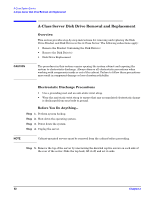
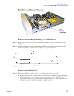
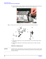
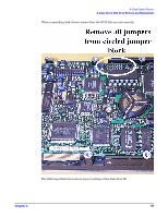
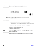
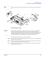
A-Class System Service A-Class Server Disk Drive Removal and Replacement NOTE This illustration of ID jumper settings is typical. Your drive may be different. Consult the literature and labels on your drive for ID setting instructions. Set the upper drive to ID to 5 Set the lower drive to ID to 6 Step 1. To Re-install the disk drive(s) follow the removal instructions in reverse. a. re-cable the disk drive(s), CAUTION Ensure that cables are connected correctly: - Match the ribbon cable connector key with the slot on the receptacle. - Match the rounded corners of the power cable connector with the rounded corners of the receptacle. Failure to observe these precautions may result in bent or broken pins. b. remount the disk drive(s) in the bracket, and c. reinstall the bracket in the server. NOTE Lift either side of the disk bracket to ensure that the tabs on the bracket are seated properly in the slots provided. The following illustration shows the SCSI address jumper settings for the disk drives. 96 Chapter 3
-
 1
1 -
2
-
3
-
4
-
5
-
6
-
7
-
8
-
9
-
10
-
11
-
12
-
13
-
14
-
15
-
16
-
17
-
18
-
19
-
20
-
21
-
22
-
23
-
24
-
25
-
26
-
27
-
28
-
29
-
30
-
31
-
32
-
33
-
34
-
35
-
36
-
37
-
38
-
39
-
40
-
41
-
42
-
43
-
44
-
45
-
46
-
47
-
48
-
49
-
50
-
51
-
52
-
53
-
54
-
55
-
56
-
57
-
58
-
59
-
60
-
61
-
62
-
63
-
64
-
65
-
66
-
67
-
68
-
69
-
70
-
71
-
72
-
73
-
74
-
75
-
76
-
77
-
78
-
79
-
80
-
81
-
82
-
83
-
84
-
85
-
86
-
87
-
88
-
89
-
90
-
 91
91 -
 92
92 -
 93
93 -
 94
94 -
 95
95 -
 96
96 -
 97
97 -
 98
98 -
 99
99 -
 100
100 -
 101
101 -
102
-
103
-
104
-
105
-
106
 |
 |