HP Rp2430 rp24xx A180 User Manual - Page 90
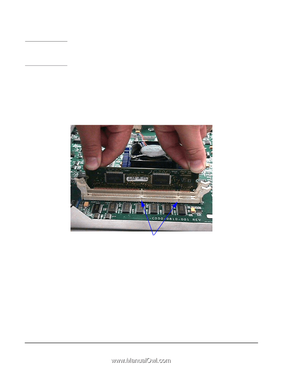
A-Class Server Cache Memory Removal and Replacement, server front, matching the keys in the connector.
 |
View all HP Rp2430 manuals
Add to My Manuals
Save this manual to your list of manuals |
Page 90 highlights
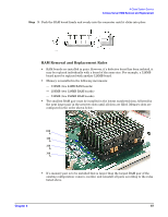
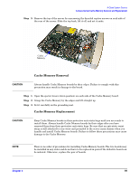
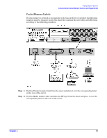
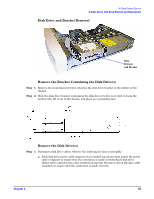
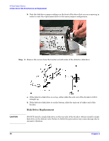
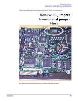
A-Class System Service A-Class Server Cache Memory Removal and Replacement NOTE A-Class servers can only use Cache Memory SIMMs with part number A5182-60002. Using Cache Memory SIMMs with any other part number may result in the server failing it's selftest. Cache Memory board replacement procedures are described as follows: Step 1. Open the ejector levers (down position). Step 2. Note the two key notches on the Cache Memory board. One key notch is in the center and one is toward the side. Orient the board so that the side key notch is toward the server front, matching the keys in the connector. Step 3. Align the board notches with the connector keys, fit the bottom sides of the board into the ejector lever slots, and insert the board into the connector. Key notches Step 4. Push the Cache memory board firmly and evenly into the connector until it clicks into place. The ejector levers will automatically close. 90 Chapter 3
-
 1
1 -
2
-
3
-
4
-
5
-
6
-
7
-
8
-
9
-
10
-
11
-
12
-
13
-
14
-
15
-
16
-
17
-
18
-
19
-
20
-
21
-
22
-
23
-
24
-
25
-
26
-
27
-
28
-
29
-
30
-
31
-
32
-
33
-
34
-
35
-
36
-
37
-
38
-
39
-
40
-
41
-
42
-
43
-
44
-
45
-
46
-
47
-
48
-
49
-
50
-
51
-
52
-
53
-
54
-
55
-
56
-
57
-
58
-
59
-
60
-
61
-
62
-
63
-
64
-
65
-
66
-
67
-
68
-
69
-
70
-
71
-
72
-
73
-
74
-
75
-
76
-
77
-
78
-
79
-
80
-
81
-
82
-
83
-
84
-
 85
85 -
 86
86 -
 87
87 -
 88
88 -
 89
89 -
 90
90 -
 91
91 -
 92
92 -
 93
93 -
 94
94 -
 95
95 -
96
-
97
-
98
-
99
-
100
-
101
-
102
-
103
-
104
-
105
-
106
 |
 |