HP Rp2430 rp24xx A180 User Manual - Page 44
Step 1., controller internal to the server. The SCSI controller address of 7 can not be modified.
 |
View all HP Rp2430 manuals
Add to My Manuals
Save this manual to your list of manuals |
Page 44 highlights
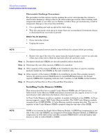
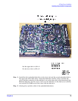
A-Class Server Installation Installing Internal Add-On Components • Use a grounding mat and an anti-static wrist strap. • Wear the anti-static wrist strap to ensure that any accumulated electrostatic charge is discharged from your body to ground. Before You Do Anything... • Power down the system. • Unplug the server. NOTE Cabinet-mounted servers must be removed from the cabinet before proceeding. • Remove the top of the server by unscrewing the knurled captive screws on each side of the rear of the server. Slide the top back, lift it off, and set it aside. Step 1. Remove the disk carrier by removing the slotted T15 TORX screw and slide the disk carrier upward and toward the power supply. Step 2. If an embedded disk is already installed, disconnect the power and data cables from that disk. Place the disk carrier on a ESD safe mat. Step 3. Set address and configuration jumpers on the disk to be installed. The lower disk is usually the boot disk and the recommended address is 6. The upper disk is recommended to be address 5. DO NOT use address 7 as this address is reserved for the SCSI controller internal to the server. The SCSI controller address of 7 can not be modified. Step 4. Check configuration jumpers existing disks. Make sure the TERMINATION ENABLED jumper is removed. NOTE The TERMINATION ENABLED jumper must be REMOVED on all embedded disk drives. Failure to remove this jumper will prevent the SCSI bus from operating properly. Symptoms include failing to boot from the embedded disk drives when external devices are connected to the "SCSI (Single Ended) 8/16/5 path". 44 Chapter 2
-
 1
1 -
2
-
3
-
4
-
5
-
6
-
7
-
8
-
9
-
10
-
11
-
12
-
13
-
14
-
15
-
16
-
17
-
18
-
19
-
20
-
21
-
22
-
23
-
24
-
25
-
26
-
27
-
28
-
29
-
30
-
31
-
32
-
33
-
34
-
35
-
36
-
37
-
38
-
 39
39 -
 40
40 -
 41
41 -
 42
42 -
 43
43 -
 44
44 -
 45
45 -
 46
46 -
 47
47 -
 48
48 -
 49
49 -
50
-
51
-
52
-
53
-
54
-
55
-
56
-
57
-
58
-
59
-
60
-
61
-
62
-
63
-
64
-
65
-
66
-
67
-
68
-
69
-
70
-
71
-
72
-
73
-
74
-
75
-
76
-
77
-
78
-
79
-
80
-
81
-
82
-
83
-
84
-
85
-
86
-
87
-
88
-
89
-
90
-
91
-
92
-
93
-
94
-
95
-
96
-
97
-
98
-
99
-
100
-
101
-
102
-
103
-
104
-
105
-
106
 |
 |