HP Rp2430 rp24xx A180 User Manual - Page 85
RAM Removal, The white stripe on the end of the board identifies the end of the board that must
 |
View all HP Rp2430 manuals
Add to My Manuals
Save this manual to your list of manuals |
Page 85 highlights
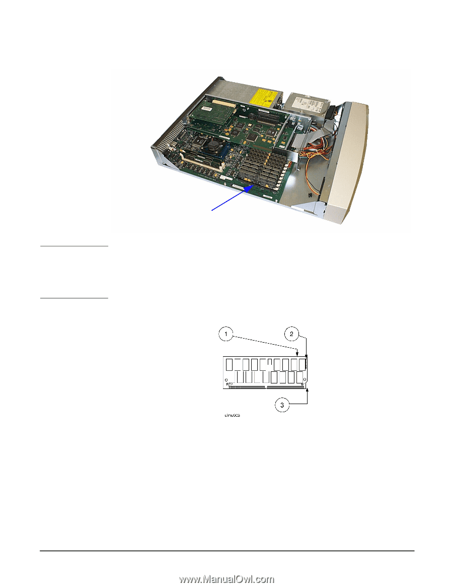
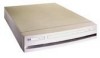
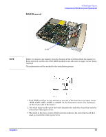
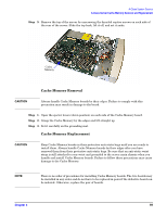
RAM Removal A-Class System Service A-Class Server RAM Removal and Replacement NOTE RAM Before you remove any memory, note the location of the slot from which the memory is being removed, and the size of the RAM (marked on one side near an upper corner) being removed. This information will be needed for the installation process. 1. Each RAM board has its size marked on one side of the board near an upper corner: 16MB, 32MB, 64MB, 128MB, or 256MB. (In the illustration shown, the marking is on the reverse side of the board.) 2. The white stripe on the end of the board identifies the end of the board that must be toward the white ejector lever. 3. The notch at the lower corner of the board also indicates the end of the board that must go toward the white ejector lever. Chapter 3 85
-
 1
1 -
2
-
3
-
4
-
5
-
6
-
7
-
8
-
9
-
10
-
11
-
12
-
13
-
14
-
15
-
16
-
17
-
18
-
19
-
20
-
21
-
22
-
23
-
24
-
25
-
26
-
27
-
28
-
29
-
30
-
31
-
32
-
33
-
34
-
35
-
36
-
37
-
38
-
39
-
40
-
41
-
42
-
43
-
44
-
45
-
46
-
47
-
48
-
49
-
50
-
51
-
52
-
53
-
54
-
55
-
56
-
57
-
58
-
59
-
60
-
61
-
62
-
63
-
64
-
65
-
66
-
67
-
68
-
69
-
70
-
71
-
72
-
73
-
74
-
75
-
76
-
77
-
78
-
79
-
 80
80 -
 81
81 -
 82
82 -
 83
83 -
 84
84 -
 85
85 -
 86
86 -
 87
87 -
 88
88 -
 89
89 -
 90
90 -
91
-
92
-
93
-
94
-
95
-
96
-
97
-
98
-
99
-
100
-
101
-
102
-
103
-
104
-
105
-
106
 |
 |