Panasonic AJ-HPD2500 Operating Instructions - Page 22
Control Reference Guide, Audio and Video Controller
 |
View all Panasonic AJ-HPD2500 manuals
Add to My Manuals
Save this manual to your list of manuals |
Page 22 highlights
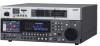
Control Reference Guide Audio and Video Controller 1 2 3 45 6 7 8 9 10 11 12 13 14 15 16 17 18 19 21 20 23 26 22 24 25 27 1. POWER switch (|/M) Turns the power on and off. ➝Refer to "Operating the AVCHD Thumbnail Screens" (page 152) Set the switch to "|" to turn it on. 3. Mode indicators 2. REMOTE button (REMOTE indicator) REMOTE button A lamp corresponding to the currently selected mode lights up. Press to enable control of this unit from an external device. 4. TCG switch REMOTE button is on: This unit can be controlled via the 9pin remote, RS-232C, parallel connector, or camera recorder. MODE (SHIFT+REMOTE) button Press the MODE and SHIFT buttons simultaneously, and the mode selection screen appears on the display panel. Select the USB device mode to connect the unit to a PC, the LAN mode to use the unit as a network server, the browser mode, or the AVCHD mode (available only when an optional board is installed). ➝Refer to "Using USB or eSATA Connectors" (page INT Synchronizes the internal time code REGEN: generator with the time code read from the P2 card. Use setup menu No. 505 (TCG REGEN) to select whether to make TC or UB the REGEN. INT Uses the internal time code generator of PRESET: this unit. Settings can be preset on the operation panel and the remote control. ➝Refer to "Time Code, User Bit and CTL" (page 195) 116) ➝Refer to "Connecting This Unit to a Network" (page 130) 22 Introduction: Control Reference Guide
-
 1
1 -
2
-
3
-
4
-
5
-
6
-
7
-
8
-
9
-
10
-
11
-
12
-
13
-
14
-
15
-
16
-
 17
17 -
 18
18 -
 19
19 -
 20
20 -
 21
21 -
 22
22 -
 23
23 -
 24
24 -
 25
25 -
 26
26 -
 27
27 -
28
-
29
-
30
-
31
-
32
-
33
-
34
-
35
-
36
-
37
-
38
-
39
-
40
-
41
-
42
-
43
-
44
-
45
-
46
-
47
-
48
-
49
-
50
-
51
-
52
-
53
-
54
-
55
-
56
-
57
-
58
-
59
-
60
-
61
-
62
-
63
-
64
-
65
-
66
-
67
-
68
-
69
-
70
-
71
-
72
-
73
-
74
-
75
-
76
-
77
-
78
-
79
-
80
-
81
-
82
-
83
-
84
-
85
-
86
-
87
-
88
-
89
-
90
-
91
-
92
-
93
-
94
-
95
-
96
-
97
-
98
-
99
-
100
-
101
-
102
-
103
-
104
-
105
-
106
-
107
-
108
-
109
-
110
-
111
-
112
-
113
-
114
-
115
-
116
-
117
-
118
-
119
-
120
-
121
-
122
-
123
-
124
-
125
-
126
-
127
-
128
-
129
-
130
-
131
-
132
-
133
-
134
-
135
-
136
-
137
-
138
-
139
-
140
-
141
-
142
-
143
-
144
-
145
-
146
-
147
-
148
-
149
-
150
-
151
-
152
-
153
-
154
-
155
-
156
-
157
-
158
-
159
-
160
-
161
-
162
-
163
-
164
-
165
-
166
-
167
-
168
-
169
-
170
-
171
-
172
-
173
-
174
-
175
-
176
-
177
-
178
-
179
-
180
-
181
-
182
-
183
-
184
-
185
-
186
-
187
-
188
-
189
-
190
-
191
-
192
-
193
-
194
-
195
-
196
-
197
-
198
-
199
-
200
-
201
-
202
-
203
-
204
-
205
-
206
-
207
-
208
-
209
-
210
-
211
-
212
-
213
-
214
-
215
-
216
-
217
-
218
-
219
-
220
-
221
-
222
-
223
-
224
-
225
-
226
 |
 |
