Panasonic AJ-HPD2500 Operating Instructions - Page 34
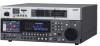
Rear Panel and Connectors Inside the Lower Front Panel, SERIAL DIGITAL COMPONENT AUDIO and VIDEO
 |
View all Panasonic AJ-HPD2500 manuals
Add to My Manuals
Save this manual to your list of manuals |
Page 34 highlights
Rear Panel and Connectors Inside the Lower Front Panel 1 2 3 45 6 Connector cover*1 7 8 10 9 11 12 13 14 15 16 17 *1: For how to open the connector cover, refer to "Opening the eSATA, USB HOST and USB DEVICE connector cover" (page 17). 1. Fan 4. TIME CODE IN/OUT connector Cools this unit. Install the unit making sure that the air vents are not blocked. If the fan stops due to a breakdown, "E-10" will appear on the counter display. While the unit will operate even when the fan has stopped, it should be shut down immediately. 2. SERIAL DIGITAL COMPONENT AUDIO and VIDEO IN/OUT connectors I/O connector for digital component audio and video data. The SD-SDI MONITOR connector outputs video signals with superimposed data. Use setup menu No.005 (SUPER) and the SUPER switch at the top of the front panel to turn superimposing on or off. ◆ NOTE: • The SD SDI MONITOR connector always outputs 480/ 59.94i or 576/50i signals. • The input digital audio signals must be synchronized with the video input signals. Otherwise, the audio signals will be affected by noise. • Use a 5C-FB compatible double-shielded cable for connection to the SERIAL DIGTAL COMPONET connector. 3. DIGITAL AUDIO IN/OUT connectors This connector inputs and outputs digital audio signals compliant with the AES/EBU standard. ◆ NOTE: • The input digital audio signals must be synchronized with the video input signals. Otherwise, the audio signals will be affected by noise. • Use double shielded cable for making connections to DIGITAL AUDIO IN/OUT connectors. This connector inputs and outputs time code signals. TIME CODE IN: TIME CODE OUT: Use to record an external time code onto P2 cards. This terminal outputs the playback time code during playback. During recording, it outputs the time code generated by the time code generator. ◆ NOTE: • When setup menu No.25 (SYSTEM FREQ) is set to 59-23, 60-24 or 60-25, time code signals cannot be input to the TIME CODE IN connector. • Use double shielded cable for making connections to TIME CODE IN/OUT connectors. 5. REF VIDEO IN connectors This connector inputs and outputs HD and SD reference video signals and outputs loop-through signals. ◆ NOTE: • It is recommended that this unit be used with a system that inputs a reference video signal since video and audio output signals may otherwise deteriorate. • Input tri-level sync signals with both positive and negative polarities as HD reference video signals. Input signals that meet the input signal and data format. ➝ For a reference signal, refer to "Example of Connections in 23.98/24/29.97/25 Hz Mode" (page 45). • Input a black burst signal that complies with SMPTE170M and ITU624-4 to use for SD reference video signals. • When no cable is connected to the REF VIDEO loop 34 Introduction: Control Reference Guide
-
 1
1 -
2
-
3
-
4
-
5
-
6
-
7
-
8
-
9
-
10
-
11
-
12
-
13
-
14
-
15
-
16
-
17
-
18
-
19
-
20
-
21
-
22
-
23
-
24
-
25
-
26
-
27
-
28
-
 29
29 -
 30
30 -
 31
31 -
 32
32 -
 33
33 -
 34
34 -
 35
35 -
 36
36 -
 37
37 -
 38
38 -
 39
39 -
40
-
41
-
42
-
43
-
44
-
45
-
46
-
47
-
48
-
49
-
50
-
51
-
52
-
53
-
54
-
55
-
56
-
57
-
58
-
59
-
60
-
61
-
62
-
63
-
64
-
65
-
66
-
67
-
68
-
69
-
70
-
71
-
72
-
73
-
74
-
75
-
76
-
77
-
78
-
79
-
80
-
81
-
82
-
83
-
84
-
85
-
86
-
87
-
88
-
89
-
90
-
91
-
92
-
93
-
94
-
95
-
96
-
97
-
98
-
99
-
100
-
101
-
102
-
103
-
104
-
105
-
106
-
107
-
108
-
109
-
110
-
111
-
112
-
113
-
114
-
115
-
116
-
117
-
118
-
119
-
120
-
121
-
122
-
123
-
124
-
125
-
126
-
127
-
128
-
129
-
130
-
131
-
132
-
133
-
134
-
135
-
136
-
137
-
138
-
139
-
140
-
141
-
142
-
143
-
144
-
145
-
146
-
147
-
148
-
149
-
150
-
151
-
152
-
153
-
154
-
155
-
156
-
157
-
158
-
159
-
160
-
161
-
162
-
163
-
164
-
165
-
166
-
167
-
168
-
169
-
170
-
171
-
172
-
173
-
174
-
175
-
176
-
177
-
178
-
179
-
180
-
181
-
182
-
183
-
184
-
185
-
186
-
187
-
188
-
189
-
190
-
191
-
192
-
193
-
194
-
195
-
196
-
197
-
198
-
199
-
200
-
201
-
202
-
203
-
204
-
205
-
206
-
207
-
208
-
209
-
210
-
211
-
212
-
213
-
214
-
215
-
216
-
217
-
218
-
219
-
220
-
221
-
222
-
223
-
224
-
225
-
226
 |
 |
