Yamaha RX-V3900BL Owner's Manual - Page 28
Using the VIDEO AUX jacks on the, front panel, Connecting the FM and AM, antennas
 |
UPC - 705105565903
View all Yamaha RX-V3900BL manuals
Add to My Manuals
Save this manual to your list of manuals |
Page 28 highlights
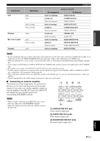
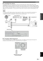
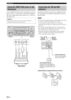
Connections Using the VIDEO AUX jacks on the front panel Use the VIDEO AUX jacks on the front panel to connect a game console or a video camera to this unit. To reproduce the source signals input at these jacks, select "V-AUX" as the input source. Caution Be sure to turn down the volume of this unit and other components before making connections. MAIN ZONE ON/OFF ON OFF MASTER INPUT AUDIO SELECT/ REC OUT MENU TONE CONTROL ENTER PRESET/TUNING/CH MEMORY SEARCH MODE STEREO/ MONO CATEGORY STRAIGHT EFFECT YPAO SILENT CINEMA MULTI ZONE S VIDEO VIDEO BAND ZONE ON/OFF ZONE CONTROLS ZONE 2 ZONE 3 L AUDIO R OPTICAL PROGRAM OPTIMIZER MIC PHONES VIDEO AUX USB INFO PURE DIRECT VOLUME S VIDEO VIDEO L AUDIO R OPTICAL Connecting the FM and AM antennas Both FM and AM indoor antennas are supplied with this unit. In general, these antennas should provide sufficient signal strength. Notes • The types of the supplied antennas and the FM antenna terminal of this unit are different depending on the models. • (Asia and General models only) Be sure to set the tuner frequency step according to the frequency spacing in your area (page 122). • The AM loop antenna should be placed away from this unit. • The AM loop antenna should always be connected, even if an outdoor AM antenna is connected to this unit. • If you experience poor reception quality, install an outdoor antenna. Consult the nearest authorized Yamaha dealer or service center about outdoor antennas. Indoor FM antenna (supplied) AM loop antenna (supplied) S V L R O ANTENNA FM GND AM 75Ω UNBAL. Optical output Audio output Video output S-Video output Game console or video camera Outdoor AM antenna Use a 5 to 10 m (16 to 33 ft) vinyl-covered wire extended outdoors from a window. Ground (GND terminal) For maximum safety and minimum interference, connect the antenna GND terminal to a good earth ground. A good earth ground is a metal stake driven into moist earth. Assembling the supplied AM loop antenna 24 En
-
 1
1 -
2
-
3
-
4
-
5
-
6
-
7
-
8
-
9
-
10
-
11
-
12
-
13
-
14
-
15
-
16
-
17
-
18
-
19
-
20
-
21
-
22
-
 23
23 -
 24
24 -
 25
25 -
 26
26 -
 27
27 -
 28
28 -
 29
29 -
 30
30 -
 31
31 -
 32
32 -
 33
33 -
34
-
35
-
36
-
37
-
38
-
39
-
40
-
41
-
42
-
43
-
44
-
45
-
46
-
47
-
48
-
49
-
50
-
51
-
52
-
53
-
54
-
55
-
56
-
57
-
58
-
59
-
60
-
61
-
62
-
63
-
64
-
65
-
66
-
67
-
68
-
69
-
70
-
71
-
72
-
73
-
74
-
75
-
76
-
77
-
78
-
79
-
80
-
81
-
82
-
83
-
84
-
85
-
86
-
87
-
88
-
89
-
90
-
91
-
92
-
93
-
94
-
95
-
96
-
97
-
98
-
99
-
100
-
101
-
102
-
103
-
104
-
105
-
106
-
107
-
108
-
109
-
110
-
111
-
112
-
113
-
114
-
115
-
116
-
117
-
118
-
119
-
120
-
121
-
122
-
123
-
124
-
125
-
126
-
127
-
128
-
129
-
130
-
131
-
132
-
133
-
134
-
135
-
136
-
137
-
138
-
139
-
140
-
141
-
142
-
143
-
144
-
145
-
146
-
147
-
148
-
149
-
150
-
151
-
152
-
153
-
154
-
155
-
156
-
157
-
158
-
159
-
160
-
161
-
162
-
163
-
164
-
165
-
166
-
167
-
168
-
169
 |
 |
