Yamaha RX-V3900BL Owner's Manual - Page 32
Using the remote control, 1] ID1/ID2 indicator
 |
UPC - 705105565903
View all Yamaha RX-V3900BL manuals
Add to My Manuals
Save this manual to your list of manuals |
Page 32 highlights
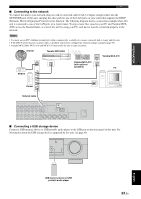
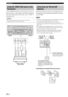
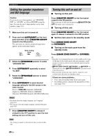
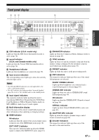
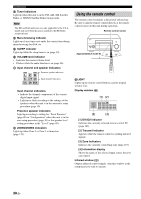
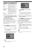
Connections n Tuner indicators Light up when this unit is in the FM, AM, XM Satellite Radio, or SIRIUS Satellite Radio tuning mode. Note The HD and TAG indicators are only applicable to the U.S.A. model and used when this unit is tuned into the HD Radio reception band. o Menu browsing indicator Lights up if any items exist under the current item during menu browsing for iPod, etc. p SLEEP indicator Lights up while the sleep timer is on (page 39). q VOLUME level indicator • Indicates the current volume level. • Flashes while the mute function is on (page 38). r Input channel and speaker indicators L CR SL LFE SR SBL SB SBR Presence speaker indicators Input channel indicators Input channel indicators • Indicate the channel components of the current digital input signal. • Light up or flash according to the settings of the speakers when this unit is in the automatic setup procedure (page 30). Presence speaker indicators Light up according to setting for "Front Presence" (page 88) in "Configuration" when this unit is in the auto setup procedure (page 30) or the speaker level setting procedure in the "Level" (page 89). s ZONE2/ZONE3 indicators Lights up when Zone 2 or Zone 3 is turned on (page 119). Using the remote control The remote control transmits a directional infrared ray. Be sure to aim the remote control directly at the remote control sensor on this unit during operation. Remote control sensor Approximately 6 m (20 ft) 30 30 6 LIGHT Lights up the remote control buttons and the display window (4). Display window (4) [1] [2] MAIN ID 1 ID 2 ZONE 2 ZONE 3 [3] [4] [1] ID1/ID2 indicator Indicates the currently selected remote control ID (page 121). [2] Transmit indicator Appears while the remote control is sending infrared signals. [3] Zone indicators Indicates the currently controlling zone (page 119). [4] Information display Shows the name of the selected input source that you can control. Infrared window (1) Outputs infrared control signals. Aim this window at the component you want to operate. 28 En
-
 1
1 -
2
-
3
-
4
-
5
-
6
-
7
-
8
-
9
-
10
-
11
-
12
-
13
-
14
-
15
-
16
-
17
-
18
-
19
-
20
-
21
-
22
-
23
-
24
-
25
-
26
-
 27
27 -
 28
28 -
 29
29 -
 30
30 -
 31
31 -
 32
32 -
 33
33 -
 34
34 -
 35
35 -
 36
36 -
 37
37 -
38
-
39
-
40
-
41
-
42
-
43
-
44
-
45
-
46
-
47
-
48
-
49
-
50
-
51
-
52
-
53
-
54
-
55
-
56
-
57
-
58
-
59
-
60
-
61
-
62
-
63
-
64
-
65
-
66
-
67
-
68
-
69
-
70
-
71
-
72
-
73
-
74
-
75
-
76
-
77
-
78
-
79
-
80
-
81
-
82
-
83
-
84
-
85
-
86
-
87
-
88
-
89
-
90
-
91
-
92
-
93
-
94
-
95
-
96
-
97
-
98
-
99
-
100
-
101
-
102
-
103
-
104
-
105
-
106
-
107
-
108
-
109
-
110
-
111
-
112
-
113
-
114
-
115
-
116
-
117
-
118
-
119
-
120
-
121
-
122
-
123
-
124
-
125
-
126
-
127
-
128
-
129
-
130
-
131
-
132
-
133
-
134
-
135
-
136
-
137
-
138
-
139
-
140
-
141
-
142
-
143
-
144
-
145
-
146
-
147
-
148
-
149
-
150
-
151
-
152
-
153
-
154
-
155
-
156
-
157
-
158
-
159
-
160
-
161
-
162
-
163
-
164
-
165
-
166
-
167
-
168
-
169
 |
 |
