Brother International HL-2600CN Users Manual - English - Page 145
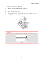
Close the Rear Access Cover., Transfer Unit groove. Set
 |
View all Brother International HL-2600CN manuals
Add to My Manuals
Save this manual to your list of manuals |
Page 145 highlights
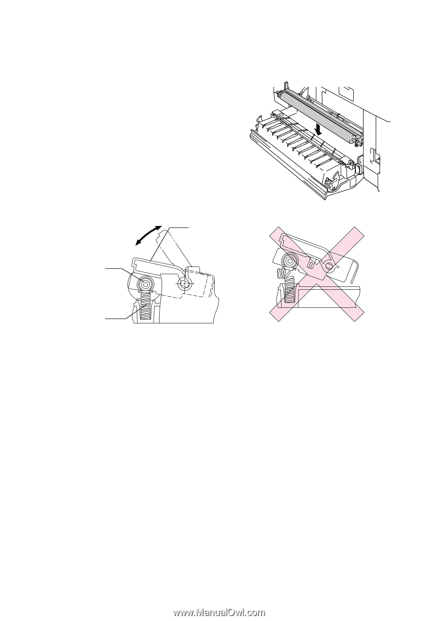
5. Install the new Transfer Roller by holding the Lock Levers of the Transfer Roller and adjusting the angle of the Transfer Roller Lever shafts (both sides) to match the Transfer Unit groove. Set the Transfer Roller onto the shafts and place the Roller onto the springs as shown below: Transfer Roller Shaft Lock Levers CHAPTER 5 MAINTENANCE Fig. 5-34 Spring Fig. 5-35 Fig. 5-36 6. Push down the Lock Lever to lock the Transfer Roller into place. 7. Close the Rear Access Cover. 8. Plug the printer into the AC outlet. 9. Press the Power button to turn on the printer. 5-33
-
 1
1 -
2
-
3
-
4
-
5
-
6
-
7
-
8
-
9
-
10
-
11
-
12
-
13
-
14
-
15
-
16
-
17
-
18
-
19
-
20
-
21
-
22
-
23
-
24
-
25
-
26
-
27
-
28
-
29
-
30
-
31
-
32
-
33
-
34
-
35
-
36
-
37
-
38
-
39
-
40
-
41
-
42
-
43
-
44
-
45
-
46
-
47
-
48
-
49
-
50
-
51
-
52
-
53
-
54
-
55
-
56
-
57
-
58
-
59
-
60
-
61
-
62
-
63
-
64
-
65
-
66
-
67
-
68
-
69
-
70
-
71
-
72
-
73
-
74
-
75
-
76
-
77
-
78
-
79
-
80
-
81
-
82
-
83
-
84
-
85
-
86
-
87
-
88
-
89
-
90
-
91
-
92
-
93
-
94
-
95
-
96
-
97
-
98
-
99
-
100
-
101
-
102
-
103
-
104
-
105
-
106
-
107
-
108
-
109
-
110
-
111
-
112
-
113
-
114
-
115
-
116
-
117
-
118
-
119
-
120
-
121
-
122
-
123
-
124
-
125
-
126
-
127
-
128
-
129
-
130
-
131
-
132
-
133
-
134
-
135
-
136
-
137
-
138
-
139
-
 140
140 -
 141
141 -
 142
142 -
 143
143 -
 144
144 -
 145
145 -
 146
146 -
 147
147 -
 148
148 -
 149
149 -
 150
150 -
151
-
152
-
153
-
154
-
155
-
156
-
157
-
158
-
159
-
160
-
161
-
162
-
163
-
164
-
165
-
166
-
167
-
168
-
169
-
170
-
171
-
172
-
173
-
174
-
175
-
176
-
177
-
178
-
179
-
180
-
181
-
182
-
183
-
184
-
185
-
186
-
187
-
188
-
189
-
190
-
191
-
192
-
193
-
194
-
195
-
196
-
197
-
198
-
199
-
200
-
201
-
202
-
203
-
204
-
205
-
206
-
207
-
208
-
209
-
210
-
211
-
212
-
213
-
214
-
215
-
216
-
217
-
218
-
219
-
220
-
221
-
222
-
223
-
224
-
225
 |
 |
CHAPTER 5 MAINTENANCE
5-33
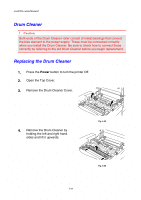
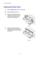
5.
Install the new Transfer Roller by
holding the Lock Levers of the
Transfer Roller and adjusting the
angle of the Transfer Roller Lever
shafts (both sides) to match the
Transfer Unit groove. Set the
Transfer Roller onto the shafts and
place the Roller onto the springs as
shown below:
Fig. 5-34
Fig. 5-35
Fig. 5-36
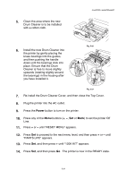
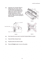
6.
Push down the Lock Lever to lock the Transfer Roller into place.
7.
Close the Rear Access Cover.
8.
Plug the printer into the AC outlet.
9.
Press the
Power
button to turn on the printer.
Transfer Roller Shaft
Spring
Lock Levers