Brother International HL-2600CN Users Manual - English - Page 165
Open the Duplex Lower Cover
 |
View all Brother International HL-2600CN manuals
Add to My Manuals
Save this manual to your list of manuals |
Page 165 highlights
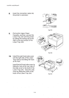
8. Insert the fixing pins at both sides of the Duplex Unit into the installation grooves in the Lower Tray Unit. CHAPTER 5 MAINTENANCE Fig. 5-68 Note Make sure that the Rear Cover of the Lower Tray Unit is closed. 9. Secure the pawl of the Duplex Unit into the rectangular hole in the back of the printer. 10. Open the Duplex Lower Cover and remove the protective parts. Close the Duplex Lower Cover. Fig. 5-69 Fig. 5-70 5-53
-
 1
1 -
2
-
3
-
4
-
5
-
6
-
7
-
8
-
9
-
10
-
11
-
12
-
13
-
14
-
15
-
16
-
17
-
18
-
19
-
20
-
21
-
22
-
23
-
24
-
25
-
26
-
27
-
28
-
29
-
30
-
31
-
32
-
33
-
34
-
35
-
36
-
37
-
38
-
39
-
40
-
41
-
42
-
43
-
44
-
45
-
46
-
47
-
48
-
49
-
50
-
51
-
52
-
53
-
54
-
55
-
56
-
57
-
58
-
59
-
60
-
61
-
62
-
63
-
64
-
65
-
66
-
67
-
68
-
69
-
70
-
71
-
72
-
73
-
74
-
75
-
76
-
77
-
78
-
79
-
80
-
81
-
82
-
83
-
84
-
85
-
86
-
87
-
88
-
89
-
90
-
91
-
92
-
93
-
94
-
95
-
96
-
97
-
98
-
99
-
100
-
101
-
102
-
103
-
104
-
105
-
106
-
107
-
108
-
109
-
110
-
111
-
112
-
113
-
114
-
115
-
116
-
117
-
118
-
119
-
120
-
121
-
122
-
123
-
124
-
125
-
126
-
127
-
128
-
129
-
130
-
131
-
132
-
133
-
134
-
135
-
136
-
137
-
138
-
139
-
140
-
141
-
142
-
143
-
144
-
145
-
146
-
147
-
148
-
149
-
150
-
151
-
152
-
153
-
154
-
155
-
156
-
157
-
158
-
159
-
 160
160 -
 161
161 -
 162
162 -
 163
163 -
 164
164 -
 165
165 -
 166
166 -
 167
167 -
 168
168 -
 169
169 -
 170
170 -
171
-
172
-
173
-
174
-
175
-
176
-
177
-
178
-
179
-
180
-
181
-
182
-
183
-
184
-
185
-
186
-
187
-
188
-
189
-
190
-
191
-
192
-
193
-
194
-
195
-
196
-
197
-
198
-
199
-
200
-
201
-
202
-
203
-
204
-
205
-
206
-
207
-
208
-
209
-
210
-
211
-
212
-
213
-
214
-
215
-
216
-
217
-
218
-
219
-
220
-
221
-
222
-
223
-
224
-
225
 |
 |
CHAPTER 5 MAINTENANCE
5-53
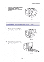
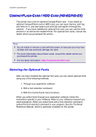
8.
Insert the fixing pins at both sides
of the Duplex Unit into the
installation grooves in the Lower
Tray Unit.
Fig. 5-68
Note
Make sure that the Rear Cover of the Lower Tray Unit is closed.
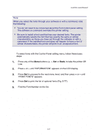
9.
Secure the pawl of the Duplex
Unit into the rectangular hole in
the back of the printer.
Fig. 5-69
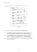
10.
Open the Duplex Lower Cover
and remove the protective parts.
Close the Duplex Lower Cover.
Fig. 5-70