Brother International HL-2600CN Users Manual - English - Page 160
Pull out the Upper Paper, Install the left hand side cover
 |
View all Brother International HL-2600CN manuals
Add to My Manuals
Save this manual to your list of manuals |
Page 160 highlights
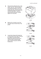
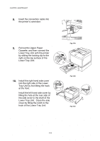
CHAPTER 5 MAINTENANCE 8. Insert the connection cable into the printer's connector. 9. Pull out the Upper Paper Cassette, and then connect the Lower Tray Unit with the printer by sliding the locking clip to the right on the top surface of the Lower Tray Unit. 10. Install the right hand side cover into the right side of the Lower Tray Unit by first fitting the hook at the front. Install the left hand side cover by fitting the hole at the rear side of the side cover to the shaft of the Lower Tray Unit. Close the side cover by fitting the notch to the hook of the Lower Tray Unit. Fig. 5-58 Fig. 5-59 Fig. 5-60 5-48
-
 1
1 -
2
-
3
-
4
-
5
-
6
-
7
-
8
-
9
-
10
-
11
-
12
-
13
-
14
-
15
-
16
-
17
-
18
-
19
-
20
-
21
-
22
-
23
-
24
-
25
-
26
-
27
-
28
-
29
-
30
-
31
-
32
-
33
-
34
-
35
-
36
-
37
-
38
-
39
-
40
-
41
-
42
-
43
-
44
-
45
-
46
-
47
-
48
-
49
-
50
-
51
-
52
-
53
-
54
-
55
-
56
-
57
-
58
-
59
-
60
-
61
-
62
-
63
-
64
-
65
-
66
-
67
-
68
-
69
-
70
-
71
-
72
-
73
-
74
-
75
-
76
-
77
-
78
-
79
-
80
-
81
-
82
-
83
-
84
-
85
-
86
-
87
-
88
-
89
-
90
-
91
-
92
-
93
-
94
-
95
-
96
-
97
-
98
-
99
-
100
-
101
-
102
-
103
-
104
-
105
-
106
-
107
-
108
-
109
-
110
-
111
-
112
-
113
-
114
-
115
-
116
-
117
-
118
-
119
-
120
-
121
-
122
-
123
-
124
-
125
-
126
-
127
-
128
-
129
-
130
-
131
-
132
-
133
-
134
-
135
-
136
-
137
-
138
-
139
-
140
-
141
-
142
-
143
-
144
-
145
-
146
-
147
-
148
-
149
-
150
-
151
-
152
-
153
-
154
-
 155
155 -
 156
156 -
 157
157 -
 158
158 -
 159
159 -
 160
160 -
 161
161 -
 162
162 -
 163
163 -
 164
164 -
 165
165 -
166
-
167
-
168
-
169
-
170
-
171
-
172
-
173
-
174
-
175
-
176
-
177
-
178
-
179
-
180
-
181
-
182
-
183
-
184
-
185
-
186
-
187
-
188
-
189
-
190
-
191
-
192
-
193
-
194
-
195
-
196
-
197
-
198
-
199
-
200
-
201
-
202
-
203
-
204
-
205
-
206
-
207
-
208
-
209
-
210
-
211
-
212
-
213
-
214
-
215
-
216
-
217
-
218
-
219
-
220
-
221
-
222
-
223
-
224
-
225
 |
 |
CHAPTER 5 MAINTENANCE
5-48
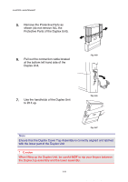
8.
Insert the connection cable into
the printer’s connector.
Fig. 5-58
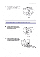
9.
Pull out the Upper Paper
Cassette, and then connect the
Lower Tray Unit with the printer
by sliding the locking clip to the
right on the top surface of the
Lower Tray Unit.
Fig. 5-59
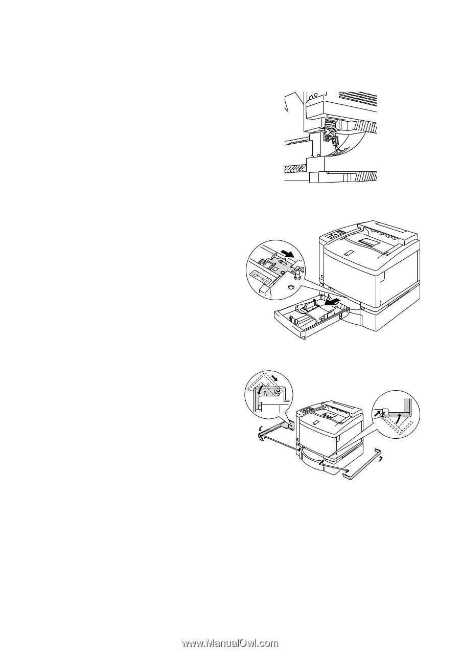
10.
Install the right hand side cover
into the right side of the Lower
Tray Unit by first fitting the hook
at the front.
Install the left hand side cover by
fitting the hole at the rear side of
the side cover to the shaft of the
Lower Tray Unit.
Close the side
cover by fitting the notch to the
hook of the Lower Tray Unit.
Fig. 5-60