Brother International HL-2600CN Users Manual - English - Page 159
Loosen the locking clip thumbscrew, the base cover at the left side of
 |
View all Brother International HL-2600CN manuals
Add to My Manuals
Save this manual to your list of manuals |
Page 159 highlights
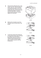
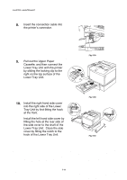
5. Check the two alignment pins on the Lower Tray Unit. Use two people to lift the printer and place it onto the Lower Tray Unit. Be sure to use the handholds located at the bottom four corners of the printer. Check to ensure that the pins are correctly aligned into the printer. 6. Remove the connector cover from the base cover at the left side of the printer. CHAPTER 5 MAINTENANCE Fig. 5-55 7. Loosen the locking clip thumbscrew on the left side of the Lower Tray Unit by rotating it counterclockwise. Rotate the locking clip and hook it onto the printer so that it hangs down, and then secure it with the thumbscrew. Fig. 5-56 Fig. 5-57 5-47
-
 1
1 -
2
-
3
-
4
-
5
-
6
-
7
-
8
-
9
-
10
-
11
-
12
-
13
-
14
-
15
-
16
-
17
-
18
-
19
-
20
-
21
-
22
-
23
-
24
-
25
-
26
-
27
-
28
-
29
-
30
-
31
-
32
-
33
-
34
-
35
-
36
-
37
-
38
-
39
-
40
-
41
-
42
-
43
-
44
-
45
-
46
-
47
-
48
-
49
-
50
-
51
-
52
-
53
-
54
-
55
-
56
-
57
-
58
-
59
-
60
-
61
-
62
-
63
-
64
-
65
-
66
-
67
-
68
-
69
-
70
-
71
-
72
-
73
-
74
-
75
-
76
-
77
-
78
-
79
-
80
-
81
-
82
-
83
-
84
-
85
-
86
-
87
-
88
-
89
-
90
-
91
-
92
-
93
-
94
-
95
-
96
-
97
-
98
-
99
-
100
-
101
-
102
-
103
-
104
-
105
-
106
-
107
-
108
-
109
-
110
-
111
-
112
-
113
-
114
-
115
-
116
-
117
-
118
-
119
-
120
-
121
-
122
-
123
-
124
-
125
-
126
-
127
-
128
-
129
-
130
-
131
-
132
-
133
-
134
-
135
-
136
-
137
-
138
-
139
-
140
-
141
-
142
-
143
-
144
-
145
-
146
-
147
-
148
-
149
-
150
-
151
-
152
-
153
-
 154
154 -
 155
155 -
 156
156 -
 157
157 -
 158
158 -
 159
159 -
 160
160 -
 161
161 -
 162
162 -
 163
163 -
 164
164 -
165
-
166
-
167
-
168
-
169
-
170
-
171
-
172
-
173
-
174
-
175
-
176
-
177
-
178
-
179
-
180
-
181
-
182
-
183
-
184
-
185
-
186
-
187
-
188
-
189
-
190
-
191
-
192
-
193
-
194
-
195
-
196
-
197
-
198
-
199
-
200
-
201
-
202
-
203
-
204
-
205
-
206
-
207
-
208
-
209
-
210
-
211
-
212
-
213
-
214
-
215
-
216
-
217
-
218
-
219
-
220
-
221
-
222
-
223
-
224
-
225
 |
 |
CHAPTER 5 MAINTENANCE
5-47
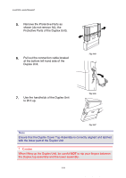
5.
Check the two alignment pins on the
Lower Tray Unit.
Use two people to
lift the printer and place it onto the
Lower Tray Unit.
Be sure to use the
handholds located at the bottom four
corners of the printer.
Check to
ensure that the pins are correctly
aligned into the printer.
Fig. 5-55
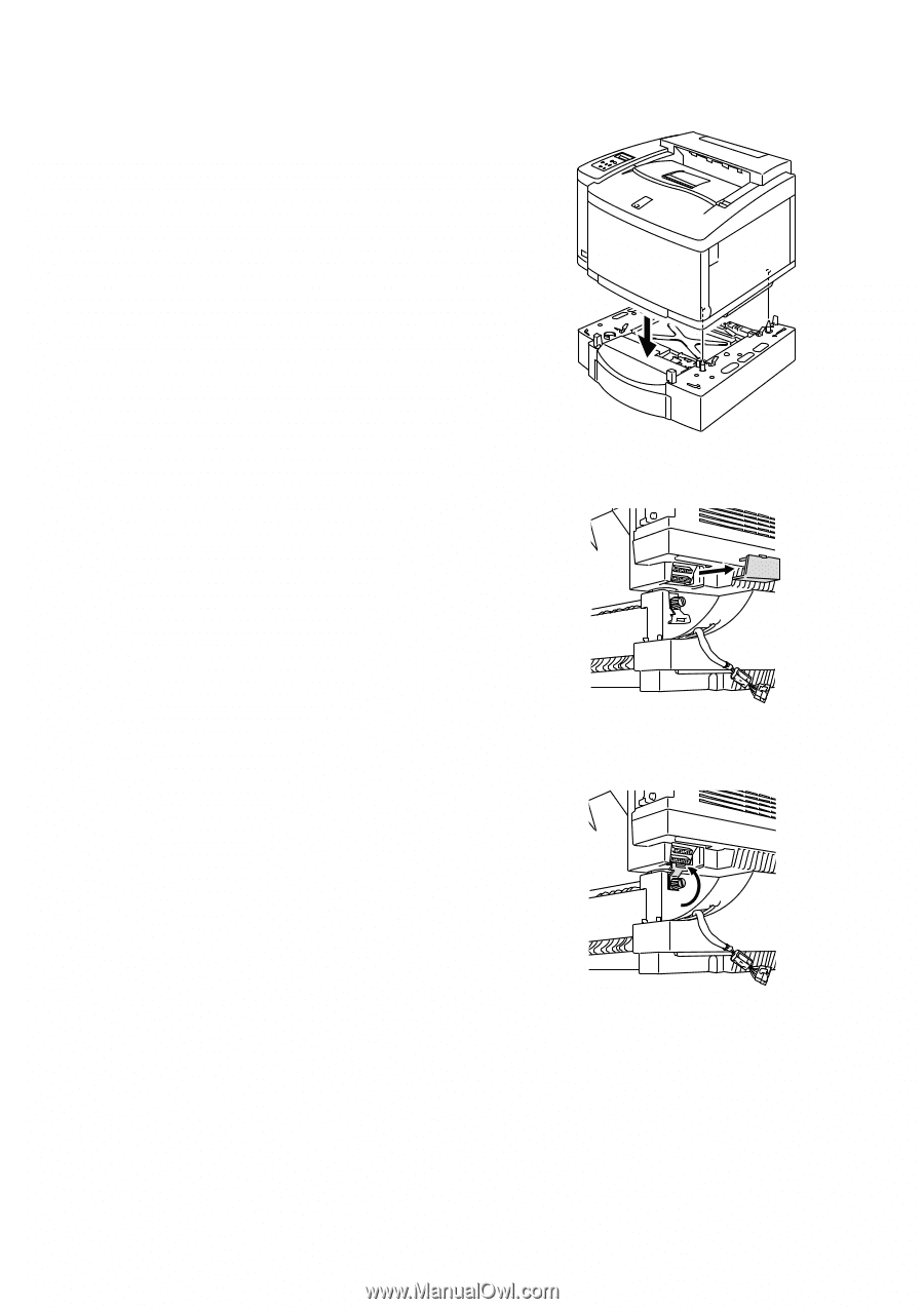
6.
Remove the connector cover from
the base cover at the left side of the
printer.
Fig. 5-56
7.
Loosen the locking clip thumbscrew
on the left side of the Lower Tray Unit
by rotating it counterclockwise.
Rotate the locking clip and hook it
onto the printer so that it hangs
down, and then secure it with the
thumbscrew.
Fig. 5-57