Cisco 7962G Administration Guide - Page 62
Verifying the Phone Startup Process
 |
UPC - 882658140341
View all Cisco 7962G manuals
Add to My Manuals
Save this manual to your list of manuals |
Page 62 highlights
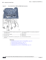
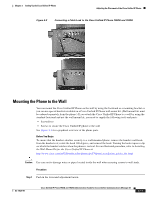
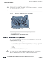
Verifying the Phone Startup Process Chapter 3 Setting Up the Cisco Unified IP Phone Step 2 Step 3 Step 4 Adjust the footstand, so it is flat against the back of the phone. Insert two screws into a wall stud, matching them to the two screw holes on the back of the footstand. The keyholes fit standard phone jack mounts. Hang the phone on the wall. Figure 3-3 Parts Used in Wall Mounting the Cisco Unified IP Phone AUX 137542 1 Footstand adjustment button-Raises and lowers adjustment plate 2 Wall mounting screw holes 3 Adjustment plate-Raises and lowers phone vertically Verifying the Phone Startup Process After the Cisco Unified IP Phone has power connected to it, the phone begins its startup process by cycling through the following steps. 1. These buttons flash on and off in sequence: - Headset (only if the handset is off-hook when the phone powers up. Hang up the handset within 3 seconds to have the phone launch its secondary load. To continue with the primary load, leave the handset off-hook.) - Mute - Speaker 2. Some or all of the line keys flash amber in sequence. Caution If the line keys flash red in sequence after flashing amber, do not power down the phone until the sequence of red flashes completes. This sequence can take several minutes to complete. 3-12 Cisco Unified IP Phone 7962G and 7942G Administration Guide for Cisco Unified Communications Manager 6.1 OL-14625-01
-
 1
1 -
2
-
3
-
4
-
5
-
6
-
7
-
8
-
9
-
10
-
11
-
12
-
13
-
14
-
15
-
16
-
17
-
18
-
19
-
20
-
21
-
22
-
23
-
24
-
25
-
26
-
27
-
28
-
29
-
30
-
31
-
32
-
33
-
34
-
35
-
36
-
37
-
38
-
39
-
40
-
41
-
42
-
43
-
44
-
45
-
46
-
47
-
48
-
49
-
50
-
51
-
52
-
53
-
54
-
55
-
56
-
 57
57 -
 58
58 -
 59
59 -
 60
60 -
 61
61 -
 62
62 -
 63
63 -
 64
64 -
 65
65 -
 66
66 -
 67
67 -
68
-
69
-
70
-
71
-
72
-
73
-
74
-
75
-
76
-
77
-
78
-
79
-
80
-
81
-
82
-
83
-
84
-
85
-
86
-
87
-
88
-
89
-
90
-
91
-
92
-
93
-
94
-
95
-
96
-
97
-
98
-
99
-
100
-
101
-
102
-
103
-
104
-
105
-
106
-
107
-
108
-
109
-
110
-
111
-
112
-
113
-
114
-
115
-
116
-
117
-
118
-
119
-
120
-
121
-
122
-
123
-
124
-
125
-
126
-
127
-
128
-
129
-
130
-
131
-
132
-
133
-
134
-
135
-
136
-
137
-
138
-
139
-
140
-
141
-
142
-
143
-
144
-
145
-
146
-
147
-
148
-
149
-
150
-
151
-
152
-
153
-
154
-
155
-
156
-
157
-
158
-
159
-
160
-
161
-
162
-
163
-
164
-
165
-
166
-
167
-
168
-
169
-
170
-
171
-
172
-
173
-
174
-
175
-
176
-
177
-
178
-
179
-
180
-
181
-
182
-
183
-
184
-
185
-
186
-
187
-
188
-
189
-
190
-
191
-
192
-
193
-
194
 |
 |
