Cisco NM-8B-U User Guide - Page 16
Blocking State, Interface 2 in Blocking State
 |
UPC - 074632001001
View all Cisco NM-8B-U manuals
Add to My Manuals
Save this manual to your list of manuals |
Page 16 highlights
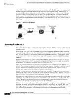
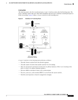
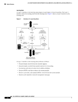
Feature Overview 16- and 36-Port Ethernet Switch Module for Cisco 2600 Series, Cisco 3600 Series, and Cisco 3700 Series Blocking State A Layer 2 interface in the blocking state does not participate in frame forwarding, as shown in Figure 5. After initialization, a BPDU is sent out to each Layer 2 interface in the switch. A switch initially assumes it is the root until it exchanges BPDUs with other switches. This exchange establishes which switch in the network is the root or root bridge. If only one switch is in the network, no exchange occurs, the forward delay timer expires, and the ports move to the listening state. A port always enters the blocking state following switch initialization. Figure 5 Interface 2 in Blocking State Segment frames Forwarding Station addresses Port 1 BPDUs Network management and data frames Filtering database System module Frame forwarding S5692 BPDUs Data frames Port 2 Network management frames Blocking Segment frames A Layer 2 interface in the blocking state performs as follows: • Discards frames received from the attached segment. • Discards frames switched from another interface for forwarding. • Does not incorporate end station location into its address database. (There is no learning on a blocking Layer 2 interface, so there is no address database update.) • Receives BPDUs and directs them to the system module. • Does not transmit BPDUs received from the system module. • Receives and responds to network management messages. Cisco IOS Release 12.2(2)XT, 12.2(8)T, and 12.2(15)ZJ 16
-
 1
1 -
2
-
3
-
4
-
5
-
6
-
7
-
8
-
9
-
10
-
 11
11 -
 12
12 -
 13
13 -
 14
14 -
 15
15 -
 16
16 -
 17
17 -
 18
18 -
 19
19 -
 20
20 -
 21
21 -
22
-
23
-
24
-
25
-
26
-
27
-
28
-
29
-
30
-
31
-
32
-
33
-
34
-
35
-
36
-
37
-
38
-
39
-
40
-
41
-
42
-
43
-
44
-
45
-
46
-
47
-
48
-
49
-
50
-
51
-
52
-
53
-
54
-
55
-
56
-
57
-
58
-
59
-
60
-
61
-
62
-
63
-
64
-
65
-
66
-
67
-
68
-
69
-
70
-
71
-
72
-
73
-
74
-
75
-
76
-
77
-
78
-
79
-
80
-
81
-
82
-
83
-
84
-
85
-
86
-
87
-
88
-
89
-
90
-
91
-
92
-
93
-
94
-
95
-
96
-
97
-
98
-
99
-
100
-
101
-
102
-
103
-
104
-
105
-
106
-
107
-
108
-
109
-
110
-
111
-
112
-
113
-
114
-
115
-
116
-
117
-
118
-
119
-
120
-
121
-
122
-
123
-
124
-
125
-
126
-
127
-
128
-
129
-
130
-
131
-
132
-
133
-
134
-
135
-
136
-
137
-
138
-
139
-
140
-
141
-
142
-
143
-
144
-
145
-
146
-
147
-
148
-
149
-
150
-
151
-
152
-
153
-
154
-
155
-
156
-
157
-
158
-
159
-
160
-
161
-
162
-
163
-
164
-
165
-
166
-
167
-
168
-
169
-
170
-
171
-
172
-
173
-
174
-
175
-
176
-
177
-
178
-
179
-
180
-
181
-
182
-
183
-
184
-
185
-
186
-
187
-
188
-
189
-
190
-
191
-
192
-
193
-
194
-
195
-
196
-
197
-
198
-
199
-
200
-
201
-
202
-
203
-
204
-
205
-
206
-
207
-
208
-
209
-
210
-
211
-
212
-
213
-
214
-
215
-
216
-
217
-
218
-
219
-
220
-
221
-
222
-
223
-
224
-
225
-
226
-
227
-
228
-
229
-
230
-
231
-
232
-
233
-
234
-
235
-
236
-
237
-
238
-
239
-
240
-
241
-
242
-
243
-
244
-
245
-
246
 |
 |
