Cisco NM-8B-U User Guide - Page 31
Queue Number, CoS Value, Weight, Basic QoS Model
 |
UPC - 074632001001
View all Cisco NM-8B-U manuals
Add to My Manuals
Save this manual to your list of manuals |
Page 31 highlights
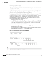
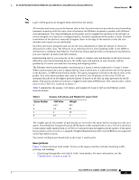
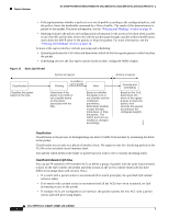
16- and 36-Port Ethernet Switch Module for Cisco 2600 Series, Cisco 3600 Series, and Cisco 3700 Series Feature Overview Note Layer 3 IPv6 packets are dropped when received by the switch. All switches and routers across the Internet rely on the class information to provide the same forwarding treatment to packets with the same class information and different treatment to packets with different class information. The class information in the packet can be assigned by end hosts or by switches or routers along the way, based on a configured policy, detailed examination of the packet, or both. Detailed examination of the packet is expected to happen closer to the edge of the network so that the core switches and routers are not overloaded. Switches and routers along the path can use the class information to limit the amount of resources allocated per traffic class. The behavior of an individual device when handling traffic in the DiffServ architecture is called per-hop behavior. If all devices along a path provide a consistent per-hop behavior, you can construct an end-to-end QoS solution. Implementing QoS in your network can be a simple or complex task and depends on the QoS features offered by your internetworking devices, the traffic types and patterns in your network, and the granularity of control you need over incoming and outgoing traffic. The Ethernet switch network module can function as a Layer 2 switch connected to a Layer 3 router. When a packet enters the Layer 2 engine directly from a switch port, it is placed into one of four queues in the dynamic, 32-MB shared memory buffer. The queue assignment is based on the dot1p value in the packet. Any voice bearer packets that come in from the Cisco IP phones on the voice VLAN are automatically placed in the highest priority (Queue 3) based on the 802.1p value generated by the IP phone. The queues are then serviced on a weighted round robin (WRR) basis. The control traffic, which uses a CoS or ToS of 3, is placed in Queue 2. Table 6 summarizes the queues, CoS values, and weights for Layer 2 QoS on the Ethernet switch network module. Table 6 Queues, CoS values, and Weights for Layer 2 QoS Queue Number 3 2 1 0 CoS Value 5,6,7 3,4 2 0,1 Weight 255 64 16 1 The weights specify the number of packets that are serviced in the queue before moving on to the next queue. Voice Realtime Transport Protocol (RTP) bearer traffic marked with a CoS or ToS of 5 and Voice Control plane traffic marked with a CoS/ToS of 3 are placed into the highest priority queues. If the queue has no packets to be serviced, it is skipped. Weighted Random Early Detection (WRED) is not supported on the Fast Ethernet ports. You cannot configure port-based QoS on the Layer 2 switch ports. Basic QoS Model Figure 15 shows the basic QoS model. Actions at the ingress interface include classifying traffic, policing, and marking: • Classifying distinguishes one kind of traffic from another. For more information, see the "Classification" section on page 32. Cisco IOS Release 12.2(2)XT, 12.2(8)T, and 12.2(15)ZJ 31
-
 1
1 -
2
-
3
-
4
-
5
-
6
-
7
-
8
-
9
-
10
-
11
-
12
-
13
-
14
-
15
-
16
-
17
-
18
-
19
-
20
-
21
-
22
-
23
-
24
-
25
-
 26
26 -
 27
27 -
 28
28 -
 29
29 -
 30
30 -
 31
31 -
 32
32 -
 33
33 -
 34
34 -
 35
35 -
 36
36 -
37
-
38
-
39
-
40
-
41
-
42
-
43
-
44
-
45
-
46
-
47
-
48
-
49
-
50
-
51
-
52
-
53
-
54
-
55
-
56
-
57
-
58
-
59
-
60
-
61
-
62
-
63
-
64
-
65
-
66
-
67
-
68
-
69
-
70
-
71
-
72
-
73
-
74
-
75
-
76
-
77
-
78
-
79
-
80
-
81
-
82
-
83
-
84
-
85
-
86
-
87
-
88
-
89
-
90
-
91
-
92
-
93
-
94
-
95
-
96
-
97
-
98
-
99
-
100
-
101
-
102
-
103
-
104
-
105
-
106
-
107
-
108
-
109
-
110
-
111
-
112
-
113
-
114
-
115
-
116
-
117
-
118
-
119
-
120
-
121
-
122
-
123
-
124
-
125
-
126
-
127
-
128
-
129
-
130
-
131
-
132
-
133
-
134
-
135
-
136
-
137
-
138
-
139
-
140
-
141
-
142
-
143
-
144
-
145
-
146
-
147
-
148
-
149
-
150
-
151
-
152
-
153
-
154
-
155
-
156
-
157
-
158
-
159
-
160
-
161
-
162
-
163
-
164
-
165
-
166
-
167
-
168
-
169
-
170
-
171
-
172
-
173
-
174
-
175
-
176
-
177
-
178
-
179
-
180
-
181
-
182
-
183
-
184
-
185
-
186
-
187
-
188
-
189
-
190
-
191
-
192
-
193
-
194
-
195
-
196
-
197
-
198
-
199
-
200
-
201
-
202
-
203
-
204
-
205
-
206
-
207
-
208
-
209
-
210
-
211
-
212
-
213
-
214
-
215
-
216
-
217
-
218
-
219
-
220
-
221
-
222
-
223
-
224
-
225
-
226
-
227
-
228
-
229
-
230
-
231
-
232
-
233
-
234
-
235
-
236
-
237
-
238
-
239
-
240
-
241
-
242
-
243
-
244
-
245
-
246
 |
 |
