Cisco NM-8B-U User Guide - Page 53
Configuring VLANs, Verifying the VLAN Configuration., Deleting a VLAN from the Database
 |
UPC - 074632001001
View all Cisco NM-8B-U manuals
Add to My Manuals
Save this manual to your list of manuals |
Page 53 highlights
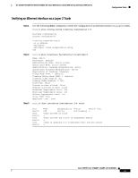
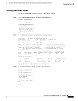
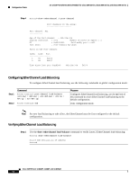
16- and 36-Port Ethernet Switch Module for Cisco 2600 Series, Cisco 3600 Series, and Cisco 3700 Series Configuration Tasks Configuring VLANs To configure an Ethernet Interface as a Layer 2 access, use the following commands beginning in EXEC mode: Step 1 Step 2 Step 3 Command Router# vlan database Router(vlan)# vlan vlan-id Router(vlan)# exit Verifying the VLAN Configuration. Purpose Enters VLAN configuration mode. Adds an Ethernet VLAN. Updates the VLAN database, propagates it throughout the administrative domain, and returns to privileged EXEC mode. Step 1 Use the show vlan name command to verify the VLAN configuration: Router# show vlan name VLAN0003 VLAN Name Status Ports 1 default active Fa1/0, Fa1/1, Fa1/2, Fa1/3 Fa1/4, Fa1/5, Fa1/6, Fa1/7 Fa1/8, Fa1/9, Fa1/10, Fa1/11 Fa1/12, Fa1/13, Fa1/14, Fa1/15 1002 fddi-default active 1003 token-ring-default active 1004 fddinet-default active 1005 trnet-default active VLAN Type SAID MTU Parent RingNo BridgeNo Stp BrdgMode Trans1 Trans2 1 enet 100001 1500 - - - - - 1002 1003 1002 fddi 101002 1500 - - - - - 1 1003 1003 tr 101003 1500 1005 0 - - srb 1 1002 1004 fdnet 101004 1500 - - 1 ibm - 0 0 1005 trnet 101005 1500 - - 1 ibm - 0 0 Router# Deleting a VLAN from the Database When you delete a VLAN from a switch that is in VTP server mode, the VLAN is removed from all switches in the VTP domain. When you delete a VLAN from a switch that is in VTP transparent mode, the VLAN is deleted only on that specific switch. You cannot delete the default VLANs for the different media types: Ethernet VLAN 1 and FDDI or Token Ring VLANs 1002 to 1005. To delete a VLAN from the database, use the following commands beginning in privileged EXEC mode: Cisco IOS Release 12.2(2)XT, 12.2(8)T, and 12.2(15)ZJ 53
-
 1
1 -
2
-
3
-
4
-
5
-
6
-
7
-
8
-
9
-
10
-
11
-
12
-
13
-
14
-
15
-
16
-
17
-
18
-
19
-
20
-
21
-
22
-
23
-
24
-
25
-
26
-
27
-
28
-
29
-
30
-
31
-
32
-
33
-
34
-
35
-
36
-
37
-
38
-
39
-
40
-
41
-
42
-
43
-
44
-
45
-
46
-
47
-
 48
48 -
 49
49 -
 50
50 -
 51
51 -
 52
52 -
 53
53 -
 54
54 -
 55
55 -
 56
56 -
 57
57 -
 58
58 -
59
-
60
-
61
-
62
-
63
-
64
-
65
-
66
-
67
-
68
-
69
-
70
-
71
-
72
-
73
-
74
-
75
-
76
-
77
-
78
-
79
-
80
-
81
-
82
-
83
-
84
-
85
-
86
-
87
-
88
-
89
-
90
-
91
-
92
-
93
-
94
-
95
-
96
-
97
-
98
-
99
-
100
-
101
-
102
-
103
-
104
-
105
-
106
-
107
-
108
-
109
-
110
-
111
-
112
-
113
-
114
-
115
-
116
-
117
-
118
-
119
-
120
-
121
-
122
-
123
-
124
-
125
-
126
-
127
-
128
-
129
-
130
-
131
-
132
-
133
-
134
-
135
-
136
-
137
-
138
-
139
-
140
-
141
-
142
-
143
-
144
-
145
-
146
-
147
-
148
-
149
-
150
-
151
-
152
-
153
-
154
-
155
-
156
-
157
-
158
-
159
-
160
-
161
-
162
-
163
-
164
-
165
-
166
-
167
-
168
-
169
-
170
-
171
-
172
-
173
-
174
-
175
-
176
-
177
-
178
-
179
-
180
-
181
-
182
-
183
-
184
-
185
-
186
-
187
-
188
-
189
-
190
-
191
-
192
-
193
-
194
-
195
-
196
-
197
-
198
-
199
-
200
-
201
-
202
-
203
-
204
-
205
-
206
-
207
-
208
-
209
-
210
-
211
-
212
-
213
-
214
-
215
-
216
-
217
-
218
-
219
-
220
-
221
-
222
-
223
-
224
-
225
-
226
-
227
-
228
-
229
-
230
-
231
-
232
-
233
-
234
-
235
-
236
-
237
-
238
-
239
-
240
-
241
-
242
-
243
-
244
-
245
-
246
 |
 |
