| Section |
Page |
| Dell™ PowerEdge™ Modular Systems |
1 |
| Contents |
3 |
| About Your System |
13 |
| Accessing System Features During Start-up |
13 |
| System Overview |
14 |
| System Control Panel Features |
16 |
| LCD Module |
18 |
| LCD Module Features |
19 |
| Using the LCD Module Menus |
19 |
| Configuration Wizard |
20 |
| Main Menu |
21 |
| LCD Setup Menu |
21 |
| Server Menu |
21 |
| Enclosure Menu |
21 |
| Blade Features |
22 |
| Using USB Diskette or USB DVD/CD Drives |
30 |
| Hard-Drive Features |
30 |
| Back-Panel Features |
33 |
| Power Supply Indicator |
35 |
| Fan Module Indicators |
36 |
| iKVM Module |
37 |
| Tiering the Avocent iKVM Switch From an Analog KVM Switch |
40 |
| Tiering the Avocent iKVM Switch From a Digital KVM Switch |
42 |
| Resynchronizing the Server List at the Remote Client Workstation |
43 |
| CMC Module |
44 |
| I/O Connectivity |
48 |
| Guidelines for Installing I/O Modules |
48 |
| General I/O Module Configuration Guidelines |
48 |
| Fabric A |
48 |
| Fabric B |
49 |
| Fabric C |
49 |
| Port Auto-Disablement in Quad-Port Network Daughter Card (M710HD Only) |
49 |
| Mezzanine Cards |
50 |
| M610x Only |
50 |
| Full-Height Blades |
51 |
| Half-Height Blades |
51 |
| I/O Module Port Mapping |
54 |
| Full-Height Blades |
54 |
| Standard LOM (Dual-Port) Mapping |
54 |
| Dual-Port Mezzanine Cards |
54 |
| Half-Height Blades |
62 |
| Standard LOM (Dual-Port) and Network Daughter Card (Quad-Port) Mapping |
62 |
| Dual-Port Mezzanine Cards |
63 |
| Mellanox M3601Q QDR Infiniband Switch I/O Module |
66 |
| Mellanox M2401G Infiniband Switch I/O Module |
67 |
| Cisco SFS M7000e Infiniband Switch Module |
69 |
| Cisco Ethernet Switch |
70 |
| PowerConnect M6348 1 Gb Ethernet Switch I/O Module |
72 |
| PowerConnect M8024 10 Gb Ethernet Switch I/O Module |
74 |
| PowerConnect M6220 Ethernet Switch Module |
76 |
| 10 Gb Ethernet Pass-Through Module II |
78 |
| 10 Gb Ethernet Pass-Through I/O Module |
80 |
| 4 Gbps Fibre Channel Pass-Through Module |
82 |
| Brocade M5424 FC8 I/O Module |
85 |
| Brocade M4424 SAN I/O Module |
88 |
| 10/100/1000 Mb Ethernet Pass-Through Module |
91 |
| LCD Status Messages |
93 |
| Viewing Status Messages |
93 |
| Removing LCD Status Messages |
93 |
| System Messages |
105 |
| Warning Messages |
105 |
| Diagnostics Messages |
125 |
| Alert Messages |
125 |
| Using the System Setup Program and UEFI Boot Manager |
127 |
| Choosing the System Boot Mode |
127 |
| Entering the System Setup Program |
128 |
| Responding to Error Messages |
128 |
| Using the System Setup Program Navigation Keys |
128 |
| System Setup Options |
129 |
| Memory Settings Screen |
130 |
| Processor Settings Screen |
131 |
| SATA Settings Screen (PowerEdge M610, M610x) |
132 |
| Boot Settings Screen |
133 |
| Integrated Devices Screen |
133 |
| PCI IRQ Assignments Screen |
135 |
| Serial Communication Screen |
135 |
| Power Management Screen (PowerEdge M910, M710, M710HD, M610 and M610x Only) |
136 |
| System Security Screen |
137 |
| Exit Screen |
138 |
| Entering the UEFI Boot Manager |
139 |
| UEFI Boot Manager Screen |
139 |
| UEFI Boot Settings Screen |
139 |
| System Utilities Screen |
140 |
| System and Setup Password Features |
140 |
| Using the System Password |
140 |
| Assigning a System Password |
140 |
| Using Your System Password to Secure Your System |
141 |
| Changing an Existing System Password |
142 |
| Using the Setup Password |
142 |
| Assigning a Setup Password |
142 |
| Operating With a Setup Password Enabled |
143 |
| Deleting or Changing an Existing Setup Password |
143 |
| Installing Blade Components |
145 |
| Recommended Tools |
145 |
| Removing and Installing a Blade |
145 |
| Removing a Blade |
145 |
| Installing a Blade |
148 |
| Removing and Installing a Blade Blank |
148 |
| Removing a Blade Blank |
148 |
| Installing a Blade Blank |
149 |
| Opening and Closing the Blade |
149 |
| Opening the Blade |
149 |
| Closing the Blade |
159 |
| System Memory |
159 |
| System Memory - PowerEdge M910 |
159 |
| General Memory Module Installation Guidelines - PowerEdge M910 |
161 |
| Non-Optimal Memory Configurations |
163 |
| Memory Sparing Support - PowerEdge M910 |
163 |
| System Memory - PowerEdge M905 |
163 |
| General Memory Module Installation Guidelines - PowerEdge M905 |
164 |
| Non-Optimal Memory Configurations |
166 |
| Memory Sparing Support - PowerEdge M905 |
166 |
| System Memory - PowerEdge M805 |
166 |
| General Memory Module Installation Guidelines - PowerEdge M805 |
167 |
| Non-Optimal Memory Configurations |
169 |
| Memory Sparing Support - PowerEdge M805 |
169 |
| System Memory - PowerEdge M710 |
170 |
| General Memory Module Installation Guidelines - PowerEdge M710 |
172 |
| Advanced ECC Mode Support - PowerEdge M710 |
172 |
| Memory Mirroring Support - PowerEdge M710 |
172 |
| Independent Channel Mode (Optimizer Mode) - PowerEdge M710 |
173 |
| System Memory - PowerEdge M710HD |
176 |
| General Memory Module Installation Guidelines - PowerEdge M710HD |
177 |
| Advanced ECC Mode Support - PowerEdge M710HD |
177 |
| Memory Mirroring Support - PowerEdge M710HD |
177 |
| Memory Sparing Support - PowerEdge M710HD |
178 |
| Independent Channel Mode (Optimizer Mode) - PowerEdge M710HD |
178 |
| System Memory - PowerEdge M610/M610x |
181 |
| General Memory Module Installation Guidelines - PowerEdge M610//M610x |
181 |
| Advanced ECC Mode Support - PowerEdge M610/M610x |
182 |
| Memory Mirroring Support - PowerEdge M610/M610x |
182 |
| Independent Channel Mode (Optimizer Mode) - PowerEdge M610/M610x |
183 |
| System Memory - PowerEdge M605 |
185 |
| General Memory Module Installation Guidelines - PowerEdge M605 |
186 |
| Single-Processor Memory Configurations |
187 |
| Dual-Processor Memory Configurations |
188 |
| Non-Optimal Memory Configurations |
189 |
| Memory Sparing Support - PowerEdge M605 |
189 |
| System Memory - PowerEdge M600 |
191 |
| General Memory Module Installation Guidelines - PowerEdge M600 |
192 |
| Non-Optimal Memory Configurations |
193 |
| Memory Sparing Support - PowerEdge M600 |
193 |
| Memory Mirroring Support - PowerEdge M600 |
193 |
| Installing Memory Modules |
194 |
| Removing Memory Modules |
195 |
| Mezzanine Interface Card (M610x Only) |
196 |
| Removing the Mezzanine Interface Card |
196 |
| Installing the Mezzanine Interface Card |
198 |
| I/O Module Mezzanine Cards |
198 |
| Mezzanine Card Installation Guidelines |
199 |
| Full-Height Blades |
199 |
| Half-Height Blades |
200 |
| Installing a Mezzanine Card |
200 |
| Removing a Mezzanine Card |
203 |
| SD Card |
204 |
| PowerEdge M905 and M805 |
204 |
| PowerEdge M910, M710, M710HD, M610, and M610x |
205 |
| SD vFlash Card (PowerEdge M910, M710, M710HD, M610, and M610x Only) |
206 |
| RAID Battery |
207 |
| Removing a RAID Battery |
207 |
| Installing the RAID Battery |
212 |
| Integrated NIC Hardware Key |
213 |
| Internal USB Key (PowerEdge M910, M710, M710HD, M610, and M610x Only) |
213 |
| iDRAC6 Enterprise Card |
214 |
| Installing an iDRAC6 Enterprise Card |
214 |
| Removing an iDRAC6 Enterprise Card |
215 |
| Network Daughter Card/LOM Riser Card (PowerEdge M710HD Only) |
216 |
| Removing the LOM Riser Card |
216 |
| Installing the LOM Riser Card |
217 |
| Expansion Cards and Expansion-Card Riser (PowerEdge M610x Only) |
217 |
| Expansion Card Installation Guidelines |
217 |
| Installing an Expansion Card |
218 |
| Removing an Expansion Card |
220 |
| Expansion-Card Riser (PowerEdge M610x Only) |
221 |
| Removing the Expansion-Card Riser |
221 |
| Installing the Expansion-Card Riser |
225 |
| Processors |
225 |
| Processor Installation Guidelines |
225 |
| PowerEdge M910 System |
225 |
| PowerEdge M905 System |
225 |
| PowerEdge M805 System |
226 |
| PowerEdge M710, M710HD, M610, M610x, and M600 Systems |
226 |
| PowerEdge M605 System |
226 |
| Removing a Processor |
226 |
| Installing a Processor |
239 |
| FlexMem Bridge (PowerEdge M910 Only) |
241 |
| Removing a FlexMem Bridge |
241 |
| Installing a FlexMem Bridge |
241 |
| HT Bridge Card (PowerEdge M905 Only) |
242 |
| Removing an HT Bridge Card |
242 |
| Installing an HT Bridge Card |
244 |
| Blade System Board NVRAM Backup Battery |
245 |
| Removing and Installing the NVRAM Backup Battery |
245 |
| Hard Drives |
247 |
| Hard Drive Installation Guidelines |
247 |
| Installing a Hard Drive |
247 |
| Removing a Hard Drive |
248 |
| Shutdown Procedure for Servicing a Hard Drive |
249 |
| Configuring the Boot Drive |
249 |
| Removing a Hard Drive From a Hard-Drive Carrier |
249 |
| Installing a Hard Drive in a Drive Carrier |
249 |
| Video Controller (PowerEdge M905, M805, M605, and M600 Only) |
251 |
| Hard-Drive Backplane |
253 |
| Blade System Board |
255 |
| Removing the System Board |
255 |
| Installing the System Board |
258 |
| Storage Controller Card |
259 |
| Removing the Storage Controller Board |
259 |
| Installing the Storage Controller Board |
260 |
| Midplane Interface Card (PowerEdge M610x) |
261 |
| Removing the Midplane Interface Card |
261 |
| Installing the Midplane Interface Card |
263 |
| Installing Enclosure Components |
265 |
| Power Supply Modules |
265 |
| System Power Guidelines |
265 |
| Power Supply Blanks |
266 |
| Removing a Power Supply Module |
266 |
| Installing a Power Supply Module |
269 |
| Fan Modules |
269 |
| Removing a Fan Module |
269 |
| Installing a Fan Module |
270 |
| CMC Module |
271 |
| Removing a CMC Module |
271 |
| Installing an SD Card in the CMC Module |
272 |
| Installing a CMC Module |
273 |
| iKVM Module |
274 |
| Removing an iKVM Module |
274 |
| Installing an iKVM Module |
274 |
| I/O Modules |
274 |
| Removing an I/O Module |
274 |
| Installing an I/O Module |
275 |
| Enclosure Bezel |
276 |
| Removing the Enclosure Bezel |
276 |
| Installing the Enclosure Bezel |
277 |
| Enclosure Midplane |
278 |
| Installing the Midplane and Front Module Cage Assembly |
280 |
| Enclosure Control Panel Assembly |
281 |
| Removing the Enclosure Control Panel |
281 |
| Installing the Enclosure Control Panel |
283 |
| LCD Module |
283 |
| Removing the LCD Module |
283 |
| Installing the LCD Module |
285 |
| Troubleshooting Your System |
287 |
| Safety First-For You and Your System |
287 |
| Start-Up Routine |
287 |
| Checking the Equipment |
288 |
| Troubleshooting External Connections |
288 |
| Troubleshooting Video |
288 |
| Troubleshooting the Keyboard |
289 |
| Troubleshooting the Mouse |
289 |
| Troubleshooting USB Devices |
290 |
| Responding to a Systems Management Alert Message |
290 |
| Troubleshooting a Wet Enclosure |
290 |
| Troubleshooting a Damaged Enclosure |
291 |
| Troubleshooting Enclosure Components |
292 |
| Troubleshooting Power Supply Modules |
292 |
| Troubleshooting Fan Modules |
293 |
| Troubleshooting the CMC Module |
293 |
| Troubleshooting the iKVM Module |
295 |
| Problem: |
295 |
| Likely Cause and Solution: |
295 |
| Example: |
295 |
| Solution: |
295 |
| Troubleshooting a Network Switch Module |
296 |
| Troubleshooting Blade Components |
297 |
| Troubleshooting Blade Memory |
297 |
| Troubleshooting Hard Drives |
298 |
| Troubleshooting Expansion Cards |
299 |
| Troubleshooting Processors |
300 |
| Troubleshooting the Blade Board |
301 |
| Troubleshooting the NVRAM Backup Battery |
302 |
| Running System Diagnostics |
303 |
| Dell PowerEdge Diagnostics |
303 |
| System Diagnostics Features |
303 |
| When to Use the System Diagnostics |
304 |
| Running the System Diagnostics |
304 |
| Running the Embedded System Diagnostics |
304 |
| From the Utility Partition |
305 |
| From a USB Flash Drive |
305 |
| System Diagnostics Testing Options |
306 |
| Using the Advanced Testing Options |
307 |
| Error Messages |
307 |
| System Board Information |
309 |
| Blade System Board Jumper Settings |
309 |
| PowerEdge M910 Jumper Settings |
309 |
| PowerEdge M905 Jumper Settings |
310 |
| PowerEdge M805 Jumper Settings |
311 |
| PowerEdge M710 Jumper Settings |
312 |
| PowerEdge M710HD Jumper Settings |
313 |
| PowerEdge M610/M610x Jumper Settings |
314 |
| PowerEdge M600 Jumper Settings |
315 |
| System Board Connectors |
316 |
| PowerEdge M910 System Board |
316 |
| PowerEdge M905 System Board |
318 |
| PowerEdge M805 System Board |
320 |
| PowerEdge M710 System Board |
322 |
| PowerEdge M710HD System Board |
324 |
| PowerEdge M610 System Board |
325 |
| PowerEdge M610x System Board |
326 |
| PowerEdge M610x Midplane Interface Card |
328 |
| PowerEdge M610x Expansion-Card Riser |
329 |
| PowerEdge M610x Mezzanine Interface Card |
330 |
| PowerEdge M605 System Board |
331 |
| PowerEdge M600 System Board |
333 |
| Disabling a Forgotten Password |
334 |
| Getting Help |
337 |
| Contacting Dell |
337 |

 1
1 280
280 281
281 282
282 283
283 284
284 285
285 286
286 287
287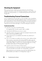 288
288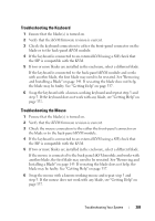 289
289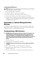 290
290

