Dell PowerEdge M420 Hardware Owner's Manual - Page 296
Troubleshooting a Network Switch Module
 |
View all Dell PowerEdge M420 manuals
Add to My Manuals
Save this manual to your list of manuals |
Page 296 highlights
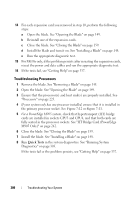
Troubleshooting a Network Switch Module NOTE: To eliminate the possibility of a hardware problem with the module or its attaching devices, first ensure that the module is properly initialized and configured. See the Configuration Guide and the documentation that came with the module before performing the following procedure. 1 Check that you have installed the module in an I/O slot that matches its fabric type. See "Supported I/O Module Configurations" on page 51. 2 Check that the passthrough module or switch ports are cabled correctly. A given mezzanine card in a full-height blade connects to two I/O ports on the two associated I/O modules. See "I/O Module Port Assignments - FullHeight Blades (not applicable to M610x)" on page 57. 3 Using the "17th blade" feature of the CMC, use the Connect Switch-X command to verify that the switch is fully booted, and verify the switch's firmware revision and IP address. 4 Verify that the switch module has a valid IP address for the subnet. Verify using the ICMP ping command. 5 Check the network connector indicators on the network switch module. • If the link indicator displays an error condition, check all cable connections. See "I/O Connectivity" on page 48 for the link indicator error conditions for your particular network switch module. • Try another connector on the external switch or hub. • If the activity indicator does not light, replace the network switch module. See "I/O Modules" on page 274. 6 Using the switch management interface, verify the switch port properties. If the switch is configured correctly, back up the switch configuration and replace the switch. See the switch module documentation for details. 7 If the blade requires a mezzanine card for a particular network switch module, ensure that the appropriate mezzanine card is installed. If so, reseat the mezzanine card. See "I/O Module Mezzanine Cards" on page 198. If the network link indicator on the blade is green, then the blade has a valid link to the appropriate network switch module. 8 Ensure that the appropriate operating system drivers are installed and that the protocol settings are configured to ensure proper communication. 296 Troubleshooting Your System
-
 1
1 -
2
-
3
-
4
-
5
-
6
-
7
-
8
-
9
-
10
-
11
-
12
-
13
-
14
-
15
-
16
-
17
-
18
-
19
-
20
-
21
-
22
-
23
-
24
-
25
-
26
-
27
-
28
-
29
-
30
-
31
-
32
-
33
-
34
-
35
-
36
-
37
-
38
-
39
-
40
-
41
-
42
-
43
-
44
-
45
-
46
-
47
-
48
-
49
-
50
-
51
-
52
-
53
-
54
-
55
-
56
-
57
-
58
-
59
-
60
-
61
-
62
-
63
-
64
-
65
-
66
-
67
-
68
-
69
-
70
-
71
-
72
-
73
-
74
-
75
-
76
-
77
-
78
-
79
-
80
-
81
-
82
-
83
-
84
-
85
-
86
-
87
-
88
-
89
-
90
-
91
-
92
-
93
-
94
-
95
-
96
-
97
-
98
-
99
-
100
-
101
-
102
-
103
-
104
-
105
-
106
-
107
-
108
-
109
-
110
-
111
-
112
-
113
-
114
-
115
-
116
-
117
-
118
-
119
-
120
-
121
-
122
-
123
-
124
-
125
-
126
-
127
-
128
-
129
-
130
-
131
-
132
-
133
-
134
-
135
-
136
-
137
-
138
-
139
-
140
-
141
-
142
-
143
-
144
-
145
-
146
-
147
-
148
-
149
-
150
-
151
-
152
-
153
-
154
-
155
-
156
-
157
-
158
-
159
-
160
-
161
-
162
-
163
-
164
-
165
-
166
-
167
-
168
-
169
-
170
-
171
-
172
-
173
-
174
-
175
-
176
-
177
-
178
-
179
-
180
-
181
-
182
-
183
-
184
-
185
-
186
-
187
-
188
-
189
-
190
-
191
-
192
-
193
-
194
-
195
-
196
-
197
-
198
-
199
-
200
-
201
-
202
-
203
-
204
-
205
-
206
-
207
-
208
-
209
-
210
-
211
-
212
-
213
-
214
-
215
-
216
-
217
-
218
-
219
-
220
-
221
-
222
-
223
-
224
-
225
-
226
-
227
-
228
-
229
-
230
-
231
-
232
-
233
-
234
-
235
-
236
-
237
-
238
-
239
-
240
-
241
-
242
-
243
-
244
-
245
-
246
-
247
-
248
-
249
-
250
-
251
-
252
-
253
-
254
-
255
-
256
-
257
-
258
-
259
-
260
-
261
-
262
-
263
-
264
-
265
-
266
-
267
-
268
-
269
-
270
-
271
-
272
-
273
-
274
-
275
-
276
-
277
-
278
-
279
-
280
-
281
-
282
-
283
-
284
-
285
-
286
-
287
-
288
-
289
-
290
-
 291
291 -
 292
292 -
 293
293 -
 294
294 -
 295
295 -
 296
296 -
 297
297 -
 298
298 -
 299
299 -
 300
300 -
 301
301 -
302
-
303
-
304
-
305
-
306
-
307
-
308
-
309
-
310
-
311
-
312
-
313
-
314
-
315
-
316
-
317
-
318
-
319
-
320
-
321
-
322
-
323
-
324
-
325
-
326
-
327
-
328
-
329
-
330
-
331
-
332
-
333
-
334
-
335
-
336
-
337
-
338
-
339
-
340
-
341
-
342
-
343
-
344
-
345
-
346
 |
 |