Dell PowerEdge MX740c EMC PowerEdge MX740c Installation and Service Manual - Page 119
System board jumper settings
 |
View all Dell PowerEdge MX740c manuals
Add to My Manuals
Save this manual to your list of manuals |
Page 119 highlights
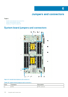
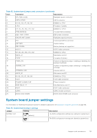
Table 13. System board jumpers and connectors (continued) Item Connector Description 2. BP_PWR_CONN Backplane power connector 3. SATA_CONN SATA connector 4. A1, A2,, A3,, A7,, A8,, A9 DIMMS for CPU1 5. CPU1 Processor 1 (blank) 6. A4, A5,, A6,, A10,, A11,, A12 DIMMS For CPU1 7. TPM_MODULE Trusted Platform Module 8. BBU_PWR_CONN BBU power connector 9. BACKPLANE SIGNAL Backplane signal connector 10. FIO Control panel(FIO) connector 11. BATTERY System battery 12. BBU SIGNAL Battery backup unit signal slot 13. AUX 0 AUX 0 cable connector 14. B4, B5,, B6,, B10,, B11,, B12 DIMMS for CPU2 15. MEZZ_A1 Mezzanine card A1 16. CPU2 Processor 2 (blank) 17. PWRD_EN System configuration jumper (enabling or disabling the password settings) 18. NVRAM_CLR System configuration jumper (retaining-/ configuration settings) 19. INTERNAL USB Internal USB 3.0 20. MEZZ_B1 Mezzanine card B1 21. B1, B2,, B3,, B7,, B8,, B9 DIMMS for CPU2 22. AUX1 AUX1 cable connector 23. POWER CONNECTOR Power connector 24. MINI_MEZZ_C1 Mini Mezzanine card C1 25. AUX2 AUX 2 cable connector 26. iDRAC iDRAC module connector 27. BOSS (M.2)/IDSDM BOSS (M.2)/IDSDM card connector System board jumper settings For information on resetting the password jumper to disable a password, see Disabling a forgotten password on page 120. Table 14. System board jumper settings Jumper Setting NVRAM_CLR (default) Description The BIOS configuration settings are retained at system boot. The BIOS configuration settings are cleared at system boot. Jumpers and connectors 119
-
 1
1 -
2
-
3
-
4
-
5
-
6
-
7
-
8
-
9
-
10
-
11
-
12
-
13
-
14
-
15
-
16
-
17
-
18
-
19
-
20
-
21
-
22
-
23
-
24
-
25
-
26
-
27
-
28
-
29
-
30
-
31
-
32
-
33
-
34
-
35
-
36
-
37
-
38
-
39
-
40
-
41
-
42
-
43
-
44
-
45
-
46
-
47
-
48
-
49
-
50
-
51
-
52
-
53
-
54
-
55
-
56
-
57
-
58
-
59
-
60
-
61
-
62
-
63
-
64
-
65
-
66
-
67
-
68
-
69
-
70
-
71
-
72
-
73
-
74
-
75
-
76
-
77
-
78
-
79
-
80
-
81
-
82
-
83
-
84
-
85
-
86
-
87
-
88
-
89
-
90
-
91
-
92
-
93
-
94
-
95
-
96
-
97
-
98
-
99
-
100
-
101
-
102
-
103
-
104
-
105
-
106
-
107
-
108
-
109
-
110
-
111
-
112
-
113
-
 114
114 -
 115
115 -
 116
116 -
 117
117 -
 118
118 -
 119
119 -
 120
120 -
 121
121 -
 122
122 -
 123
123 -
 124
124 -
125
-
126
-
127
-
128
-
129
-
130
-
131
-
132
-
133
-
134
-
135
 |
 |
