Dell PowerEdge MX740c EMC PowerEdge MX740c Installation and Service Manual - Page 44
Installing the sled into enclosure, Next steps
 |
View all Dell PowerEdge MX740c manuals
Add to My Manuals
Save this manual to your list of manuals |
Page 44 highlights
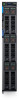
NOTE: The color of the I/O connector cover may differ. CAUTION: If you are permanently removing the sled, install a sled blank promptly. Operating the enclosure without a blank, for an extended time can result in overheating or performance loss. Next steps 1. Install the sled or the sled blank into the enclosure. Installing the sled into enclosure Prerequisites 1. Follow the safety guidelines listed in Safety instructions on page 41. CAUTION: To prevent damage to the I/O connectors, do not touch the connectors or the connector pins. Steps 1. Remove the I/O connector cover from the I/O connector(s) and store for future use. CAUTION: To protect the I/O connector pins, install the I/O connector cover every time a sled is removed from the enclosure. Figure 14. Removing the I/O connector cover from sled NOTE: The color of the I/O connector cover may differ. 2. Press the blue release button on the sled to release the sled handle. 3. Holding the sled with both hands, align the sled with the compute sled-bay in the enclosure. 4. Slide the sled into the enclosure, until the sled handle is in the lock position. 5. Push the sled handle inwards so that it locks into place to secure the sled in the enclosure. 44 Installing and removing system components
-
 1
1 -
2
-
3
-
4
-
5
-
6
-
7
-
8
-
9
-
10
-
11
-
12
-
13
-
14
-
15
-
16
-
17
-
18
-
19
-
20
-
21
-
22
-
23
-
24
-
25
-
26
-
27
-
28
-
29
-
30
-
31
-
32
-
33
-
34
-
35
-
36
-
37
-
38
-
 39
39 -
 40
40 -
 41
41 -
 42
42 -
 43
43 -
 44
44 -
 45
45 -
 46
46 -
 47
47 -
 48
48 -
 49
49 -
50
-
51
-
52
-
53
-
54
-
55
-
56
-
57
-
58
-
59
-
60
-
61
-
62
-
63
-
64
-
65
-
66
-
67
-
68
-
69
-
70
-
71
-
72
-
73
-
74
-
75
-
76
-
77
-
78
-
79
-
80
-
81
-
82
-
83
-
84
-
85
-
86
-
87
-
88
-
89
-
90
-
91
-
92
-
93
-
94
-
95
-
96
-
97
-
98
-
99
-
100
-
101
-
102
-
103
-
104
-
105
-
106
-
107
-
108
-
109
-
110
-
111
-
112
-
113
-
114
-
115
-
116
-
117
-
118
-
119
-
120
-
121
-
122
-
123
-
124
-
125
-
126
-
127
-
128
-
129
-
130
-
131
-
132
-
133
-
134
-
135
 |
 |
