Dell PowerEdge R760XA Installation and Service Manual - Page 119
Removing the expansion card risers, Table 76. Config 1. RF1B+RF2B+R1V+R4T continued
 |
View all Dell PowerEdge R760XA manuals
Add to My Manuals
Save this manual to your list of manuals |
Page 119 highlights
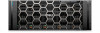
Table 76. Config 1. RF1B+RF2B+R1V+R4T (continued) Card type Slot priority Mellanox (NIC: NDR200) 1 Mellanox (NIC: NDR) 1 Mellanox (NIC: HDR100 VPI) 2, 7, 1 Mellanox (NIC: 100Gb) 2, 7, 1 Broadcom (NIC: 100Gb) 2, 7, 1 Intel (NIC: 100Gb) 2, 7, 1 Intel (NIC: 25Gb) 2, 7, 1 Broadcom (NIC: 25Gb) 2, 7, 1 Mellanox (NIC: 25Gb) 2, 7, 1 Broadcom (HBA:FC64) 2, 7, 1 Broadcom (HBA: FC32) 2, 7, 1 Qlogic (Marvell) (HBA: FC32) 1 Broadcom (NIC: 10Gb) 2, 7, 1 Intel (NIC: 10Gb) 2, 7, 1 Intel (NIC: 1Gb) 2, 7, 1 Broadcom (NIC: 1Gb) 2, 7, 1 Maximum number of cards 1 1 3 3 3 3 3 3 3 3 3 1 3 3 3 3 Removing the expansion card risers Prerequisites 1. Follow the safety guidelines listed in the Safety instructions. 2. Follow the procedure listed in the Before working inside your system. 3. If applicable, disconnect the cables from the expansion card or system board. NOTE: Only Riser 1 and Riser 4 are supported. WARNING: If BOSS-N1 module is installed, ensure to disconnect the BOSS-N1 power cable before removing riser 3 blank, Riser 1 or Riser 4. Figure 81. Disconnecting the BOSS-N1 power cable Installing and removing system components 119
-
 1
1 -
2
-
3
-
4
-
5
-
6
-
7
-
8
-
9
-
10
-
11
-
12
-
13
-
14
-
15
-
16
-
17
-
18
-
19
-
20
-
21
-
22
-
23
-
24
-
25
-
26
-
27
-
28
-
29
-
30
-
31
-
32
-
33
-
34
-
35
-
36
-
37
-
38
-
39
-
40
-
41
-
42
-
43
-
44
-
45
-
46
-
47
-
48
-
49
-
50
-
51
-
52
-
53
-
54
-
55
-
56
-
57
-
58
-
59
-
60
-
61
-
62
-
63
-
64
-
65
-
66
-
67
-
68
-
69
-
70
-
71
-
72
-
73
-
74
-
75
-
76
-
77
-
78
-
79
-
80
-
81
-
82
-
83
-
84
-
85
-
86
-
87
-
88
-
89
-
90
-
91
-
92
-
93
-
94
-
95
-
96
-
97
-
98
-
99
-
100
-
101
-
102
-
103
-
104
-
105
-
106
-
107
-
108
-
109
-
110
-
111
-
112
-
113
-
 114
114 -
 115
115 -
 116
116 -
 117
117 -
 118
118 -
 119
119 -
 120
120 -
 121
121 -
 122
122 -
 123
123 -
 124
124 -
125
-
126
-
127
-
128
-
129
-
130
-
131
-
132
-
133
-
134
-
135
-
136
-
137
-
138
-
139
-
140
-
141
-
142
-
143
-
144
-
145
-
146
-
147
-
148
-
149
-
150
-
151
-
152
-
153
-
154
-
155
-
156
-
157
-
158
-
159
-
160
-
161
-
162
-
163
-
164
-
165
-
166
-
167
-
168
-
169
-
170
-
171
-
172
-
173
-
174
-
175
-
176
-
177
-
178
-
179
-
180
-
181
-
182
-
183
-
184
-
185
-
186
-
187
-
188
-
189
-
190
-
191
-
192
-
193
-
194
-
195
-
196
-
197
-
198
-
199
-
200
-
201
-
202
-
203
-
204
-
205
-
206
 |
 |
