Dell PowerEdge R760XA Installation and Service Manual - Page 37
Memory Settings, Table 35. System Information details continued, Table 36. Memory Settings details
 |
View all Dell PowerEdge R760XA manuals
Add to My Manuals
Save this manual to your list of manuals |
Page 37 highlights
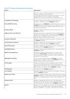
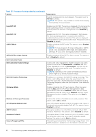
Table 35. System Information details (continued) Option Description System BIOS Version Specifies the BIOS version installed on the system. System Management Engine Version Specifies the current version of the Management Engine firmware. System Service Tag Specifies the system Service Tag. System Manufacturer Specifies the name of the system manufacturer. System Manufacturer Contact Information Specifies the contact information of the system manufacturer. System CPLD Version Specifies the current version of the system Complex Programmable Logic Device (CPLD) firmware. UEFI Compliance Version Specifies the UEFI compliance level of the system firmware. Memory Settings To view the Memory Settings screen, power on the system, press F2, and click System Setup Main Menu > System BIOS > Memory Settings. Table 36. Memory Settings details Option System Memory Size System Memory Type System Memory Speed Video Memory System Memory Testing Memory Operating Mode Current State of Memory Operating Mode Fault Resilient Mode Memory Size[%] Node Interleaving ADDDC Setting Description Specifies the size of the system memory. Specifies the type of memory installed in the system. Specifies the speed of the system memory. Specifies the size video memory. Specifies whether the system memory tests are run during system boot. The two options available are Enabled and Disabled. This option is set to Disabled by default. This field selects the memory operating mode. This feature is active only if a valid memory configuration is detected. When Optimizer Mode is enabled, the DRAM controllers operate independently in 64-bit mode and provide optimized memory performance. When Dell Fault Resilient Mode (FRM) is enabled, a percentage of the total installed memory is configured to create a fault resilient zone starting from lowest system memory address for use by select hypervisors for host virtualization resilience. Specify the FRM percentage by using the Fault Resilient Mode Memory Size[%] feature. When Dell NUMA Fault Resilient Mode (FRM) is enabled, a percentage of the installed memory in every NUMA node is configured to create a fault resilient zone for use by select hypervisors for host virtualization resilience. Specify the FRM percentage by using the Fault Resilient Mode Memory Size[%] feature. Specifies the current state of the memory operating mode. Select to define the percent of total memory size that must be used by the fault resilient mode, when selected in the Memory Operating mode. When Fault Resilient Mode is not selected, this option is grayed out and not used by Fault Resilient Mode. Enables or disables the Node interleaving option. Specifies if the NonUniform Memory Architecture (NUMA) is supported. If this field is set to Enabled, memory interleaving is supported if a symmetric memory configuration is installed. If the field is set to Disabled, the system supports NUMA (asymmetric) memory configurations. This option is set to Disabled by default. Enables or disables ADDDC Setting feature. When Adaptive Double DRAM Device Correction (ADDDC) is enabled, failing DRAMs are dynamically Pre-operating system management applications 37
-
 1
1 -
2
-
3
-
4
-
5
-
6
-
7
-
8
-
9
-
10
-
11
-
12
-
13
-
14
-
15
-
16
-
17
-
18
-
19
-
20
-
21
-
22
-
23
-
24
-
25
-
26
-
27
-
28
-
29
-
30
-
31
-
 32
32 -
 33
33 -
 34
34 -
 35
35 -
 36
36 -
 37
37 -
 38
38 -
 39
39 -
 40
40 -
 41
41 -
 42
42 -
43
-
44
-
45
-
46
-
47
-
48
-
49
-
50
-
51
-
52
-
53
-
54
-
55
-
56
-
57
-
58
-
59
-
60
-
61
-
62
-
63
-
64
-
65
-
66
-
67
-
68
-
69
-
70
-
71
-
72
-
73
-
74
-
75
-
76
-
77
-
78
-
79
-
80
-
81
-
82
-
83
-
84
-
85
-
86
-
87
-
88
-
89
-
90
-
91
-
92
-
93
-
94
-
95
-
96
-
97
-
98
-
99
-
100
-
101
-
102
-
103
-
104
-
105
-
106
-
107
-
108
-
109
-
110
-
111
-
112
-
113
-
114
-
115
-
116
-
117
-
118
-
119
-
120
-
121
-
122
-
123
-
124
-
125
-
126
-
127
-
128
-
129
-
130
-
131
-
132
-
133
-
134
-
135
-
136
-
137
-
138
-
139
-
140
-
141
-
142
-
143
-
144
-
145
-
146
-
147
-
148
-
149
-
150
-
151
-
152
-
153
-
154
-
155
-
156
-
157
-
158
-
159
-
160
-
161
-
162
-
163
-
164
-
165
-
166
-
167
-
168
-
169
-
170
-
171
-
172
-
173
-
174
-
175
-
176
-
177
-
178
-
179
-
180
-
181
-
182
-
183
-
184
-
185
-
186
-
187
-
188
-
189
-
190
-
191
-
192
-
193
-
194
-
195
-
196
-
197
-
198
-
199
-
200
-
201
-
202
-
203
-
204
-
205
-
206
 |
 |
