Dell PowerEdge R760XA Installation and Service Manual - Page 160
Intrusion switch, Removing the intrusion switch module
 |
View all Dell PowerEdge R760XA manuals
Add to My Manuals
Save this manual to your list of manuals |
Page 160 highlights
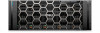
Intrusion switch This is a service technician replaceable part only. Removing the intrusion switch module Prerequisites 1. Follow the safety guidelines listed in the Safety instructions. 2. Follow the procedure listed in the Before working inside your system. 3. Remove the expansion card risers. NOTE: Ensure that you note the routing of the cables as you remove them from the system board. Route the cables properly when you replace them to prevent cables from being pinched or crimped. Steps 1. Disconnect the intrusion switch cable from the connector on the rear I/O board. 2. Using a Phillips #1 screwdriver, loosen the screw on the intrusion switch module. 3. Slide the intrusion switch module out of the slot on the system. NOTE: The numbers on the image do not depict the exact steps. The numbers are for representation of sequence. Figure 132. Removing the intrusion switch module Next steps 1. Replace the intrusion switch module. Installing the intrusion switch module Prerequisites 1. Follow the safety guidelines listed in the Safety instructions. 2. Follow the procedure listed in Before working inside your system. 160 Installing and removing system components
-
 1
1 -
2
-
3
-
4
-
5
-
6
-
7
-
8
-
9
-
10
-
11
-
12
-
13
-
14
-
15
-
16
-
17
-
18
-
19
-
20
-
21
-
22
-
23
-
24
-
25
-
26
-
27
-
28
-
29
-
30
-
31
-
32
-
33
-
34
-
35
-
36
-
37
-
38
-
39
-
40
-
41
-
42
-
43
-
44
-
45
-
46
-
47
-
48
-
49
-
50
-
51
-
52
-
53
-
54
-
55
-
56
-
57
-
58
-
59
-
60
-
61
-
62
-
63
-
64
-
65
-
66
-
67
-
68
-
69
-
70
-
71
-
72
-
73
-
74
-
75
-
76
-
77
-
78
-
79
-
80
-
81
-
82
-
83
-
84
-
85
-
86
-
87
-
88
-
89
-
90
-
91
-
92
-
93
-
94
-
95
-
96
-
97
-
98
-
99
-
100
-
101
-
102
-
103
-
104
-
105
-
106
-
107
-
108
-
109
-
110
-
111
-
112
-
113
-
114
-
115
-
116
-
117
-
118
-
119
-
120
-
121
-
122
-
123
-
124
-
125
-
126
-
127
-
128
-
129
-
130
-
131
-
132
-
133
-
134
-
135
-
136
-
137
-
138
-
139
-
140
-
141
-
142
-
143
-
144
-
145
-
146
-
147
-
148
-
149
-
150
-
151
-
152
-
153
-
154
-
 155
155 -
 156
156 -
 157
157 -
 158
158 -
 159
159 -
 160
160 -
 161
161 -
 162
162 -
 163
163 -
 164
164 -
 165
165 -
166
-
167
-
168
-
169
-
170
-
171
-
172
-
173
-
174
-
175
-
176
-
177
-
178
-
179
-
180
-
181
-
182
-
183
-
184
-
185
-
186
-
187
-
188
-
189
-
190
-
191
-
192
-
193
-
194
-
195
-
196
-
197
-
198
-
199
-
200
-
201
-
202
-
203
-
204
-
205
-
206
 |
 |
