Dell PowerEdge R760XA Installation and Service Manual - Page 85
Removing the drive backplane, x 2.5-inch NVMe drive backplane
 |
View all Dell PowerEdge R760XA manuals
Add to My Manuals
Save this manual to your list of manuals |
Page 85 highlights
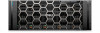
Figure 47. 8 x 2.5-inch NVMe drive backplane 1. BP_PWR_CTRL 2. BP_DST_SA1 (PERC to backplane) 3. BP_PWR_1 (backplane power and signal cable to system board) Figure 48. 8 x 2.5-inch drive backplane 1. BP_PWR_CTRL 3. BP_DST_PA1 (PCIe/NVMe connector) 5. BP_ DST_PA2 (PCIe/NVMe connector) 7. BP_DST_PB2 (PCIe/NVMe connector) 2. BP_DST_SA1 (PERC to backplane) 4. BP_ DST_PB1 (PCIe/NVMe connector) 6. BP_PWR_1 (backplane power and signal cable to system board) Removing the drive backplane Prerequisites CAUTION: To prevent damage to the drives and backplane, remove the drives from the system before removing the backplane. CAUTION: Note the number of each drive and temporarily label them before you remove the drive so that you can reinstall them in the same location. NOTE: The procedure to remove the backplane is similar for all backplane configurations. 1. Follow the safety guidelines listed in the Safety instructions. 2. Follow the procedure listed in the Before working inside your system. 3. Remove the drive backplane cover. 4. If installed, remove the air shroud. 5. Remove the cooling fan cage assembly. 6. Remove the drives. 7. If required, remove the rear mounting front PERC module. 8. Observe and disconnect the drive backplane cables from the connector on the system board and backplane. Installing and removing system components 85
-
 1
1 -
2
-
3
-
4
-
5
-
6
-
7
-
8
-
9
-
10
-
11
-
12
-
13
-
14
-
15
-
16
-
17
-
18
-
19
-
20
-
21
-
22
-
23
-
24
-
25
-
26
-
27
-
28
-
29
-
30
-
31
-
32
-
33
-
34
-
35
-
36
-
37
-
38
-
39
-
40
-
41
-
42
-
43
-
44
-
45
-
46
-
47
-
48
-
49
-
50
-
51
-
52
-
53
-
54
-
55
-
56
-
57
-
58
-
59
-
60
-
61
-
62
-
63
-
64
-
65
-
66
-
67
-
68
-
69
-
70
-
71
-
72
-
73
-
74
-
75
-
76
-
77
-
78
-
79
-
 80
80 -
 81
81 -
 82
82 -
 83
83 -
 84
84 -
 85
85 -
 86
86 -
 87
87 -
 88
88 -
 89
89 -
 90
90 -
91
-
92
-
93
-
94
-
95
-
96
-
97
-
98
-
99
-
100
-
101
-
102
-
103
-
104
-
105
-
106
-
107
-
108
-
109
-
110
-
111
-
112
-
113
-
114
-
115
-
116
-
117
-
118
-
119
-
120
-
121
-
122
-
123
-
124
-
125
-
126
-
127
-
128
-
129
-
130
-
131
-
132
-
133
-
134
-
135
-
136
-
137
-
138
-
139
-
140
-
141
-
142
-
143
-
144
-
145
-
146
-
147
-
148
-
149
-
150
-
151
-
152
-
153
-
154
-
155
-
156
-
157
-
158
-
159
-
160
-
161
-
162
-
163
-
164
-
165
-
166
-
167
-
168
-
169
-
170
-
171
-
172
-
173
-
174
-
175
-
176
-
177
-
178
-
179
-
180
-
181
-
182
-
183
-
184
-
185
-
186
-
187
-
188
-
189
-
190
-
191
-
192
-
193
-
194
-
195
-
196
-
197
-
198
-
199
-
200
-
201
-
202
-
203
-
204
-
205
-
206
 |
 |
