Epson R260 Service Manual - Page 6

Adjustment, Maintenance, Appendix, EPSON Stylus Photo R260/R265/R270, R360/R380/R390 - waste pad

Page 6 highlights

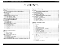
EPSON Stylus Photo R260/R265/R270, R360/R380/R390 4.2.8 Right Front Housing / Left Front Housing 72 4.2.9 Front Housing 73 4.3 Removing Control Boards 76 4.3.1 Removing the USB Board (R260/R265/R270 only 76 4.3.2 Removing the Main Board Unit 78 4.3.3 Disassembling the Main Board Unit 80 4.3.4 Removing the Card Board (R360/R380/R390 only 82 4.3.5 Disassembling the Panel Unit 83 4.3.6 Middle Housing 86 4.4 Removing the Printer Mechanism 87 4.4.1 Removing the Printer Mechanism 87 4.5 Disassembly of the Printer Mechanism 89 4.5.1 CR Scale 89 4.5.2 APG Unit 90 4.5.3 Printhead 91 4.5.4 Waste Ink Pad 94 4.5.5 P/S Assy 94 4.5.6 Stacker Assy 95 4.5.7 Ink System 97 4.5.8 CR Motor 99 4.5.9 EJ Frame Assy 100 4.5.10 PF Encoder / PF Scale / PF Motor 102 4.5.11 ASF Unit 104 4.5.12 CR Unit 105 4.5.13 Upper Paper Guide 108 4.5.14 Front Paper Guide Assy/APG Sensor Assy 109 4.5.15 CDR Guide Detection Assy 111 Chapter 5 Adjustment 5.1 Adjustment Items and Overview 113 5.1.1 Servicing Adjustment Item List 113 5.1.2 Replacement Part Adjustment Items 116 5.2 Adjustment by Using Adjustment Program 118 5.2.1 Top Margin Adjustment 118 5.2.2 Head angular adjustment 118 5.2.3 Bi-D Adjustment 119 5.2.4 PW Adjustment/First Dot Adjustment 120 5.2.5 PF Adjustment 121 5.2.6 PG Adjustment 122 Revision B 5.3 Banding Reduction System (BRS) Adjustment/ Paper Feed Amount Profile (PFP) Correction 124 5.3.1 Overview 124 5.3.2 Adjustment Procedure 125 Chapter 6 Maintenance 6.1 Overview ...130 6.1.1 Cleaning 130 6.1.2 Service Maintenance 130 6.1.3 Lubrication 131 Chapter 7 Appendix 7.1 Exploded Diagram / Parts List 138 7.2 Electrical Circuits 138 7

  • 1
  • 2
  • 3
  • 4
  • 5
  • 6
  • 7
  • 8
  • 9
  • 10
  • 11
  • 12
  • 13
  • 14
  • 15
  • 16
  • 17
  • 18
  • 19
  • 20
  • 21
  • 22
  • 23
  • 24
  • 25
  • 26
  • 27
  • 28
  • 29
  • 30
  • 31
  • 32
  • 33
  • 34
  • 35
  • 36
  • 37
  • 38
  • 39
  • 40
  • 41
  • 42
  • 43
  • 44
  • 45
  • 46
  • 47
  • 48
  • 49
  • 50
  • 51
  • 52
  • 53
  • 54
  • 55
  • 56
  • 57
  • 58
  • 59
  • 60
  • 61
  • 62
  • 63
  • 64
  • 65
  • 66
  • 67
  • 68
  • 69
  • 70
  • 71
  • 72
  • 73
  • 74
  • 75
  • 76
  • 77
  • 78
  • 79
  • 80
  • 81
  • 82
  • 83
  • 84
  • 85
  • 86
  • 87
  • 88
  • 89
  • 90
  • 91
  • 92
  • 93
  • 94
  • 95
  • 96
  • 97
  • 98
  • 99
  • 100
  • 101
  • 102
  • 103
  • 104
  • 105
  • 106
  • 107
  • 108
  • 109
  • 110
  • 111
  • 112
  • 113
  • 114
  • 115
  • 116
  • 117
  • 118
  • 119
  • 120
  • 121
  • 122
  • 123
  • 124
  • 125
  • 126
  • 127
  • 128
  • 129
  • 130
  • 131
  • 132
  • 133
  • 134
  • 135
  • 136
  • 137
  • 138
  • 139
  • 140
  • 141
  • 142
  • 143
  • 144
  • 145
  • 146
  • 147
  • 148
  • 149
  • 150

EPSON Stylus Photo R260/R265/R270, R360/R380/R390
Revision B
7
4.2.8
Right Front Housing / Left Front Housing
..............................................
72
4.2.9
Front Housing
..........................................................................................
73
4.3
Removing Control Boards
..................................................................................
76
4.3.1
Removing the USB Board (R260/R265/R270 only)
...............................
76
4.3.2
Removing the Main Board Unit
..............................................................
78
4.3.3
Disassembling the Main Board Unit
.......................................................
80
4.3.4
Removing the Card Board (R360/R380/R390 only)
...............................
82
4.3.5
Disassembling the Panel Unit
..................................................................
83
4.3.6
Middle Housing
......................................................................................
86
4.4
Removing the Printer Mechanism
......................................................................
87
4.4.1
Removing the Printer Mechanism
...........................................................
87
4.5
Disassembly of the Printer Mechanism
.............................................................
89
4.5.1
CR Scale
.................................................................................................
89
4.5.2
APG Unit
................................................................................................
90
4.5.3
Printhead
.................................................................................................
91
4.5.4
Waste Ink Pad
.........................................................................................
94
4.5.5
P/S Assy
..................................................................................................
94
4.5.6
Stacker Assy
...........................................................................................
95
4.5.7
Ink System
..............................................................................................
97
4.5.8
CR Motor
................................................................................................
99
4.5.9
EJ Frame Assy
.......................................................................................
100
4.5.10
PF Encoder / PF Scale / PF Motor
......................................................
102
4.5.11
ASF Unit
.............................................................................................
104
4.5.12
CR Unit
...............................................................................................
105
4.5.13
Upper Paper Guide
.............................................................................
108
4.5.14
Front Paper Guide Assy/APG Sensor Assy
........................................
109
4.5.15
CDR Guide Detection Assy
.................................................................
111
Chapter 5
Adjustment
5.1
Adjustment Items and Overview
......................................................................
113
5.1.1
Servicing Adjustment Item List
.............................................................
113
5.1.2
Replacement Part Adjustment Items
.....................................................
116
5.2
Adjustment by Using Adjustment Program
.....................................................
118
5.2.1
Top Margin Adjustment
........................................................................
118
5.2.2
Head angular adjustment
.......................................................................
118
5.2.3
Bi-D Adjustment
...................................................................................
119
5.2.4
PW Adjustment/First Dot Adjustment
..................................................
120
5.2.5
PF Adjustment
.......................................................................................
121
5.2.6
PG Adjustment
......................................................................................
122
5.3
Banding Reduction System (BRS) Adjustment/ Paper Feed Amount
Profile (PFP) Correction
...................................................................................
124
5.3.1 Overview
...............................................................................................
124
5.3.2
Adjustment Procedure
...........................................................................
125
Chapter 6
Maintenance
6.1 Overview
..........................................................................................................
130
6.1.1 Cleaning
.................................................................................................
130
6.1.2
Service Maintenance
.............................................................................
130
6.1.3 Lubrication
............................................................................................
131
Chapter 7
Appendix
7.1
Exploded Diagram / Parts List
.........................................................................
138
7.2
Electrical Circuits
.............................................................................................
138