HP 6120XG HP ProCurve Series 6120 Blade Switches Advanced Traffic Management G - Page 111
MSTP Structure, Hello Time, Forward Delay, - cross connect examples
 |
View all HP 6120XG manuals
Add to My Manuals
Save this manual to your list of manuals |
Page 111 highlights
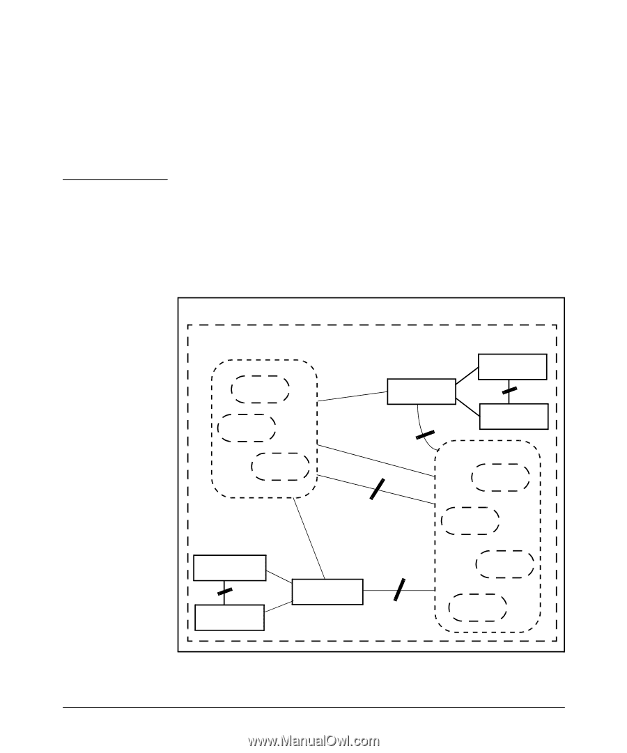
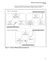
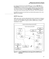
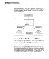
Multiple Instance Spanning-Tree Operation 802.1s Multiple Spanning Tree Protocol (MSTP) In a mesh environment, the default MSTP timer settings (Hello Time and Forward Delay) are usually adequate for MSTP operation. Because a packet crossing a mesh may traverse several links within the mesh, using smallerthan-default settings for the MSTP Hello Time and Forward Delay timers can cause unnecessary topology changes and end-node connectivity problems. For MSTP information beyond what is provided in this manual, refer to the IEEE 802.1s standard. MSTP Structure MSTP maps active, separate paths through separate spanning tree instances and between MST regions. Each MST region comprises one or more MSTP switches. Note that MSTP recognizes an STP or RSTP LAN as a distinct spanning-tree region. Common and Internal Spanning Tree (CIST) MST Region IST Instance MSTI (Optional) MSTI (Optional) Common Spanning Tree (CST) Switch Running STP Switch Running STP Switch Running STP MST Region IST Instance Switch Running RSTP Switch Running RSTP Switch Running RSTP MSTI (Optional) MSTI (Optional) MSTI (Optional) Figure 4-2. Example of MSTP Network with Legacy STP and RSTP Devices Connected 4-7
-
 1
1 -
2
-
3
-
4
-
5
-
6
-
7
-
8
-
9
-
10
-
11
-
12
-
13
-
14
-
15
-
16
-
17
-
18
-
19
-
20
-
21
-
22
-
23
-
24
-
25
-
26
-
27
-
28
-
29
-
30
-
31
-
32
-
33
-
34
-
35
-
36
-
37
-
38
-
39
-
40
-
41
-
42
-
43
-
44
-
45
-
46
-
47
-
48
-
49
-
50
-
51
-
52
-
53
-
54
-
55
-
56
-
57
-
58
-
59
-
60
-
61
-
62
-
63
-
64
-
65
-
66
-
67
-
68
-
69
-
70
-
71
-
72
-
73
-
74
-
75
-
76
-
77
-
78
-
79
-
80
-
81
-
82
-
83
-
84
-
85
-
86
-
87
-
88
-
89
-
90
-
91
-
92
-
93
-
94
-
95
-
96
-
97
-
98
-
99
-
100
-
101
-
102
-
103
-
104
-
105
-
 106
106 -
 107
107 -
 108
108 -
 109
109 -
 110
110 -
 111
111 -
 112
112 -
 113
113 -
 114
114 -
 115
115 -
 116
116 -
117
-
118
-
119
-
120
-
121
-
122
-
123
-
124
-
125
-
126
-
127
-
128
-
129
-
130
-
131
-
132
-
133
-
134
-
135
-
136
-
137
-
138
-
139
-
140
-
141
-
142
-
143
-
144
-
145
-
146
-
147
-
148
-
149
-
150
-
151
-
152
-
153
-
154
-
155
-
156
-
157
-
158
-
159
-
160
-
161
-
162
-
163
-
164
-
165
-
166
-
167
-
168
-
169
-
170
-
171
-
172
-
173
-
174
-
175
-
176
-
177
-
178
-
179
-
180
-
181
-
182
-
183
-
184
-
185
-
186
-
187
-
188
-
189
-
190
-
191
-
192
-
193
-
194
-
195
-
196
-
197
-
198
-
199
-
200
-
201
-
202
-
203
-
204
-
205
-
206
-
207
-
208
-
209
-
210
-
211
-
212
-
213
-
214
-
215
-
216
-
217
-
218
-
219
-
220
-
221
-
222
-
223
-
224
-
225
-
226
-
227
-
228
-
229
-
230
-
231
-
232
-
233
-
234
-
235
-
236
-
237
-
238
-
239
-
240
-
241
-
242
-
243
-
244
-
245
-
246
-
247
-
248
-
249
-
250
-
251
-
252
-
253
-
254
-
255
-
256
-
257
-
258
-
259
-
260
-
261
-
262
-
263
-
264
-
265
-
266
-
267
-
268
-
269
-
270
-
271
-
272
-
273
-
274
-
275
-
276
-
277
-
278
-
279
-
280
-
281
-
282
-
283
-
284
-
285
-
286
-
287
-
288
 |
 |