HP 6120XG HP ProCurve Series 6120 Blade Switches Advanced Traffic Management G - Page 36
Overlapping (Tagged) VLANs, Example of Overlapping VLANs Using the Same Server
 |
View all HP 6120XG manuals
Add to My Manuals
Save this manual to your list of manuals |
Page 36 highlights
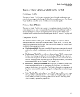
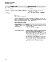
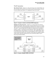
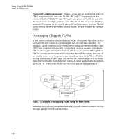
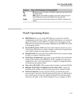
Static Virtual LANs (VLANs) Static VLAN Operation Protocol VLAN Environment. Figure 2-2 can also be applied to a protocol VLAN environment. In this case, VLANs "W" and "X" represent routable protocol VLANs. VLANs "Y" and "Z" can be any protocol VLAN. As noted for the discussion of multiple port-based VLANs, VLAN 1 is not shown. Enabling internal (IP) routing on the switch allows IP traffic to move between VLANs on the switch. However, routable, non-IP traffic always requires an external router. Overlapping (Tagged) VLANs A port can be a member of more than one VLAN of the same type if the device to which the port connects complies with the 802.1Q VLAN standard. For example, a port connected to a central server using a network interface card (NIC) that complies with the 802.1Q standard can be a member of multiple VLANs, allowing members of multiple VLANs to use the server. Although these VLANs cannot communicate with each other through the server, they can all access the server over the same connection from the switch. Where VLANs overlap in this way, VLAN "tags" are used in the individual packets to distinguish between traffic from different VLANs. A VLAN tag includes the particular VLAN I.D. (VID) of the VLAN on which the packet was generated. ProCurve Switch 802.1Q-Compliant Server Figure 2-3. Example of Overlapping VLANs Using the Same Server Similarly, using 802.1Q-compliant switches, you can connect multiple VLANs through a single switch-to-switch link. 2-10
-
 1
1 -
2
-
3
-
4
-
5
-
6
-
7
-
8
-
9
-
10
-
11
-
12
-
13
-
14
-
15
-
16
-
17
-
18
-
19
-
20
-
21
-
22
-
23
-
24
-
25
-
26
-
27
-
28
-
29
-
30
-
 31
31 -
 32
32 -
 33
33 -
 34
34 -
 35
35 -
 36
36 -
 37
37 -
 38
38 -
 39
39 -
 40
40 -
 41
41 -
42
-
43
-
44
-
45
-
46
-
47
-
48
-
49
-
50
-
51
-
52
-
53
-
54
-
55
-
56
-
57
-
58
-
59
-
60
-
61
-
62
-
63
-
64
-
65
-
66
-
67
-
68
-
69
-
70
-
71
-
72
-
73
-
74
-
75
-
76
-
77
-
78
-
79
-
80
-
81
-
82
-
83
-
84
-
85
-
86
-
87
-
88
-
89
-
90
-
91
-
92
-
93
-
94
-
95
-
96
-
97
-
98
-
99
-
100
-
101
-
102
-
103
-
104
-
105
-
106
-
107
-
108
-
109
-
110
-
111
-
112
-
113
-
114
-
115
-
116
-
117
-
118
-
119
-
120
-
121
-
122
-
123
-
124
-
125
-
126
-
127
-
128
-
129
-
130
-
131
-
132
-
133
-
134
-
135
-
136
-
137
-
138
-
139
-
140
-
141
-
142
-
143
-
144
-
145
-
146
-
147
-
148
-
149
-
150
-
151
-
152
-
153
-
154
-
155
-
156
-
157
-
158
-
159
-
160
-
161
-
162
-
163
-
164
-
165
-
166
-
167
-
168
-
169
-
170
-
171
-
172
-
173
-
174
-
175
-
176
-
177
-
178
-
179
-
180
-
181
-
182
-
183
-
184
-
185
-
186
-
187
-
188
-
189
-
190
-
191
-
192
-
193
-
194
-
195
-
196
-
197
-
198
-
199
-
200
-
201
-
202
-
203
-
204
-
205
-
206
-
207
-
208
-
209
-
210
-
211
-
212
-
213
-
214
-
215
-
216
-
217
-
218
-
219
-
220
-
221
-
222
-
223
-
224
-
225
-
226
-
227
-
228
-
229
-
230
-
231
-
232
-
233
-
234
-
235
-
236
-
237
-
238
-
239
-
240
-
241
-
242
-
243
-
244
-
245
-
246
-
247
-
248
-
249
-
250
-
251
-
252
-
253
-
254
-
255
-
256
-
257
-
258
-
259
-
260
-
261
-
262
-
263
-
264
-
265
-
266
-
267
-
268
-
269
-
270
-
271
-
272
-
273
-
274
-
275
-
276
-
277
-
278
-
279
-
280
-
281
-
282
-
283
-
284
-
285
-
286
-
287
-
288
 |
 |