HP Color LaserJet 9500 Service Manual - Page 223
message, Check connections at the controller PCA.
 |
View all HP Color LaserJet 9500 manuals
Add to My Manuals
Save this manual to your list of manuals |
Page 223 highlights
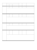
Table 29. Control panel and event log messages-3,000-sheet stacker (continued) Event log, if connected to Control panel message 9000 9500, 9500mfp, 9050, 9000mfp 9050/9040mfp User LED Service LED Description 66.12.40 Output device failure 66.12.40 66.12.40 66.12.40 Amber solid Red (5 blinks) The offset module does not reach the offset position. Either the offset module or the controller circuitry of the module is damaged. Recommended action: NOTE: The device is operable under this condition. However, the device might offset poorly or fail to offset 1 Analyze the event log for frequency of the error message. 2 Turn the printer or MFP off and then on again to see whether the error is present during the power-on sequence. 3 Replace the offset module as needed. NOTE: When more than five errors in a row of this type are logged, it is an indication that the offset module has failed. 4 Replace the controller PCA as needed. 66.12.70 Output device failure 66.12.70 66.12.70 66.12.70 Amber solid Red (7 blinks) An EEPROM error exists. One or more cells in the internal EEPROM on the controller PCA is damaged. Recommended action: NOTE: The device might be operable under this condition. However, because failure of EEPROM affects the offset feature, the device might offset poorly or fail to offset. 1 Analyze the event log for frequency of the error message. 2 Turn the printer or MFP off and then on again to see whether the error is present during the power-on sequence. 3 Check the Jet-Link cable connections. 4 If the message persists, then replace the controller PCA. External device None initializing None None Amber blinking Red solid The device is performing its power-on sequence along with the printer or MFP. Recommended action: This message should appear for a few minutes, if the message persists, then check the following: 1 Make sure that the power cord is well connected. 2 Check connections at the controller PCA. 3 Replace the Jet-Link cable as needed. 4 Replace the controller PCA as needed. Optional bin 1 full None None None Amber blinking Green solid The face-up bin is full. More than 125 sheets of 75-g/m2 (20-lb) media has been collected (or fewer than 125 sheets, if heavier media is in use). Recommended action: 1 Remove all media from the face up bin. 2 If the message persists when the bin is empty, then make sure that the FLFUF actuator (see page 83) moves freely. 3 Check the functionality of the FLFUF sensor by using the sensor test (see "Face-up bin-full sensor test" on page 240). 4 If the FLFUF actuator moves freely and the FLFUF sensor operates correctly, but the message persists, then replace the flipper assembly. ENWW Chapter 7 Troubleshooting 221
-
 1
1 -
2
-
3
-
4
-
5
-
6
-
7
-
8
-
9
-
10
-
11
-
12
-
13
-
14
-
15
-
16
-
17
-
18
-
19
-
20
-
21
-
22
-
23
-
24
-
25
-
26
-
27
-
28
-
29
-
30
-
31
-
32
-
33
-
34
-
35
-
36
-
37
-
38
-
39
-
40
-
41
-
42
-
43
-
44
-
45
-
46
-
47
-
48
-
49
-
50
-
51
-
52
-
53
-
54
-
55
-
56
-
57
-
58
-
59
-
60
-
61
-
62
-
63
-
64
-
65
-
66
-
67
-
68
-
69
-
70
-
71
-
72
-
73
-
74
-
75
-
76
-
77
-
78
-
79
-
80
-
81
-
82
-
83
-
84
-
85
-
86
-
87
-
88
-
89
-
90
-
91
-
92
-
93
-
94
-
95
-
96
-
97
-
98
-
99
-
100
-
101
-
102
-
103
-
104
-
105
-
106
-
107
-
108
-
109
-
110
-
111
-
112
-
113
-
114
-
115
-
116
-
117
-
118
-
119
-
120
-
121
-
122
-
123
-
124
-
125
-
126
-
127
-
128
-
129
-
130
-
131
-
132
-
133
-
134
-
135
-
136
-
137
-
138
-
139
-
140
-
141
-
142
-
143
-
144
-
145
-
146
-
147
-
148
-
149
-
150
-
151
-
152
-
153
-
154
-
155
-
156
-
157
-
158
-
159
-
160
-
161
-
162
-
163
-
164
-
165
-
166
-
167
-
168
-
169
-
170
-
171
-
172
-
173
-
174
-
175
-
176
-
177
-
178
-
179
-
180
-
181
-
182
-
183
-
184
-
185
-
186
-
187
-
188
-
189
-
190
-
191
-
192
-
193
-
194
-
195
-
196
-
197
-
198
-
199
-
200
-
201
-
202
-
203
-
204
-
205
-
206
-
207
-
208
-
209
-
210
-
211
-
212
-
213
-
214
-
215
-
216
-
217
-
 218
218 -
 219
219 -
 220
220 -
 221
221 -
 222
222 -
 223
223 -
 224
224 -
 225
225 -
 226
226 -
 227
227 -
 228
228 -
229
-
230
-
231
-
232
-
233
-
234
-
235
-
236
-
237
-
238
-
239
-
240
-
241
-
242
-
243
-
244
-
245
-
246
-
247
-
248
-
249
-
250
-
251
-
252
-
253
-
254
-
255
-
256
-
257
-
258
-
259
-
260
-
261
-
262
-
263
-
264
-
265
-
266
-
267
-
268
-
269
-
270
-
271
-
272
-
273
-
274
-
275
-
276
-
277
-
278
-
279
-
280
-
281
-
282
-
283
-
284
-
285
-
286
-
287
-
288
-
289
-
290
-
291
-
292
-
293
-
294
-
295
-
296
-
297
-
298
-
299
-
300
 |
 |
