HP GbE2c HP GbE2c Ethernet Blade Switch for c-Class BladeSystem ISCLI Referenc - Page 110
Layer 3 configuration, IP interface configuration
 |
UPC - 808736802215
View all HP GbE2c manuals
Add to My Manuals
Save this manual to your list of manuals |
Page 110 highlights
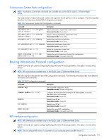
Table 116 VLAN Configuration commands Command show vlan [] Description Displays the current VLAN configuration. Command mode: All IMPORTANT: All ports must belong to at least one VLAN. Any port which is removed from a VLAN and which is not a member of any other VLAN is automatically added to default VLAN 1. You cannot remove a port from VLAN 1 if the port has no membership in any other VLAN. Also, you cannot add a port to more than one VLAN unless the port has VLAN tagging turned on. Layer 3 configuration The following table describes basic Layer 3 Configuration commands. The following sections provide more detailed information and commands. Table 117 L3 Configuration commands Command Description interface ip {} Enter IP Interface mode. Command mode: Global configuration *route-map Enter IP Route Map mode. Command mode: Global configuration *router rip Enter Router RIP mode. Command mode: Global configuration *router ospf Enter Router OSPF mode. Command mode: Global configuration *router vrrp Enter VRRP configuration mode. Command mode: Global configuration *ip router-id Sets the router ID. Command mode: Global configuration show layer3 Displays the current IP configuration. Command mode: All except User EXEC * indicates command modes that apply only to the GbE2c Ethernet Blade Switch. IP interface configuration The switch can be configured with up to 256 IP interfaces. Each IP interface represents the switch on an IP subnet on your network. The IP Interface option is disabled by default. The following table describes the IP Interface Configuration commands. Table 118 IP Interface Configuration commands Command interface ip {} ip address {}{} vlan {} enable Description Enter IP interface mode. Command mode: Global configuration Configures the IP address and mask of the switch interface using dotted decimal notation. Command mode: Interface IP Configures the VLAN number for this interface. Each interface can belong to one VLAN, though any VLAN can have multiple IP interfaces in it. Command mode: Interface IP Enables this IP interface. Command mode: Interface IP Configuration Commands 110
-
 1
1 -
2
-
3
-
4
-
5
-
6
-
7
-
8
-
9
-
10
-
11
-
12
-
13
-
14
-
15
-
16
-
17
-
18
-
19
-
20
-
21
-
22
-
23
-
24
-
25
-
26
-
27
-
28
-
29
-
30
-
31
-
32
-
33
-
34
-
35
-
36
-
37
-
38
-
39
-
40
-
41
-
42
-
43
-
44
-
45
-
46
-
47
-
48
-
49
-
50
-
51
-
52
-
53
-
54
-
55
-
56
-
57
-
58
-
59
-
60
-
61
-
62
-
63
-
64
-
65
-
66
-
67
-
68
-
69
-
70
-
71
-
72
-
73
-
74
-
75
-
76
-
77
-
78
-
79
-
80
-
81
-
82
-
83
-
84
-
85
-
86
-
87
-
88
-
89
-
90
-
91
-
92
-
93
-
94
-
95
-
96
-
97
-
98
-
99
-
100
-
101
-
102
-
103
-
104
-
 105
105 -
 106
106 -
 107
107 -
 108
108 -
 109
109 -
 110
110 -
 111
111 -
 112
112 -
 113
113 -
 114
114 -
 115
115 -
116
-
117
-
118
-
119
-
120
-
121
-
122
-
123
-
124
-
125
-
126
-
127
-
128
-
129
-
130
-
131
-
132
-
133
-
134
-
135
-
136
-
137
-
138
-
139
-
140
-
141
-
142
-
143
-
144
-
145
-
146
-
147
-
148
-
149
-
150
-
151
-
152
-
153
 |
 |