HP GbE2c HP GbE2c Ethernet Blade Switch for c-Class BladeSystem ISCLI Referenc - Page 126
Virtual Router Redundancy Protocol configuration, VRRP Virtual Router configuration
 |
UPC - 808736802215
View all HP GbE2c manuals
Add to My Manuals
Save this manual to your list of manuals |
Page 126 highlights
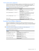
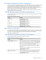
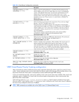
Virtual Router Redundancy Protocol configuration Virtual Router Redundancy Protocol (VRRP) support on the GbE2c Ethernet Blade switch provides redundancy between routers in a LAN. This is accomplished by configuring the same virtual router IP address and ID number on each participating VRRP-capable routing device. One of the virtual routers is then elected as the master, based on a number of priority criteria, and assumes control of the shared virtual router IP address. If the master fails, one of the backup virtual routers will assume routing authority and take control of the virtual router IP address. By default, VRRP is disabled. For more information on VRRP, see the "High Availability" chapter in the HP c-Class GbE2c Ethernet Blade Switch Application Guide. NOTE: VRRP commands are available only on the GbE2c Layer 2/3 Ethernet Blade Switch. The following table describes the basic VRRP Configuration commands. The following sections provide more detailed information and commands. Table 145 VRRP Configuration commands Command router vrrp enable no enable show ip vrrp Description Enter VRRP configuration mode. Command mode: Router VRRP Globally enables VRRP on this switch. Command mode: Router VRRP Globally disables VRRP on this switch. Command mode: Router VRRP Displays the current VRRP parameters. Command mode: All except User EXEC VRRP Virtual Router configuration Virtual Router commands are used for configuring up to 255 virtual routers for this switch. A virtual router is defined by its virtual router ID and an IP address. On each VRRP-capable routing device participating in redundancy for this virtual router, a virtual router will be configured to share the same virtual router ID and IP address. Virtual routers are disabled by default. NOTE: VRRP commands are available only on the GbE2c Layer 2/3 Ethernet Blade Switch. The following table describes the Virtual Router Configuration commands. Table 146 Virtual Router Configuration commands Command virtual-router virtual-router-id [no] virtual-router address Description Defines the virtual router ID. This is used in conjunction with addr (below) to define a virtual router on this switch. To create a pool of VRRP-enabled routing devices which can provide redundancy to each other, each participating VRRP device must be configured with the same virtual router: one that shares the same virtual router ID and address combination. The vrid for standard virtual routers (where the virtual router IP address is not the same as any virtual server) can be any integer between 1 and 255. The default value is 1. All virtual router ID values must be unique within the VLAN to which the virtual router's IP interface belongs. Command mode: Router VRRP Defines the IP address for this virtual router using dotted decimal notation. This is used in conjunction with the vrid (above) to configure the same virtual router on each participating VRRP device. The default address is 0.0.0.0 Command mode: Router VRRP Configuration Commands 126
-
 1
1 -
2
-
3
-
4
-
5
-
6
-
7
-
8
-
9
-
10
-
11
-
12
-
13
-
14
-
15
-
16
-
17
-
18
-
19
-
20
-
21
-
22
-
23
-
24
-
25
-
26
-
27
-
28
-
29
-
30
-
31
-
32
-
33
-
34
-
35
-
36
-
37
-
38
-
39
-
40
-
41
-
42
-
43
-
44
-
45
-
46
-
47
-
48
-
49
-
50
-
51
-
52
-
53
-
54
-
55
-
56
-
57
-
58
-
59
-
60
-
61
-
62
-
63
-
64
-
65
-
66
-
67
-
68
-
69
-
70
-
71
-
72
-
73
-
74
-
75
-
76
-
77
-
78
-
79
-
80
-
81
-
82
-
83
-
84
-
85
-
86
-
87
-
88
-
89
-
90
-
91
-
92
-
93
-
94
-
95
-
96
-
97
-
98
-
99
-
100
-
101
-
102
-
103
-
104
-
105
-
106
-
107
-
108
-
109
-
110
-
111
-
112
-
113
-
114
-
115
-
116
-
117
-
118
-
119
-
120
-
 121
121 -
 122
122 -
 123
123 -
 124
124 -
 125
125 -
 126
126 -
 127
127 -
 128
128 -
 129
129 -
 130
130 -
 131
131 -
132
-
133
-
134
-
135
-
136
-
137
-
138
-
139
-
140
-
141
-
142
-
143
-
144
-
145
-
146
-
147
-
148
-
149
-
150
-
151
-
152
-
153
 |
 |